
Aluminum bonding alloy, and clad material and aluminum bonding composite material each having bonding alloy layer made of the alloy

a technology of aluminum bonding alloy and alloy layer, which is applied in the direction of metal-working apparatus, non-electric welding apparatus, metallic material coating process, etc., can solve the problems of significant deformation of bondability, poor mechanical strength and corrosion resistance of aluminum material (a single-layer material made of aluminum), and impairing the bonding strength present, etc., to achieve excellent corrosion resistance, workability and bondability

Active Publication Date: 2014-11-11
NEOMAX MATERIALS
View PDF13 Cites 10 Cited by
  • Summary
  • Abstract
  • Description
  • Claims
  • Application Information

AI Technical Summary

Benefits of technology

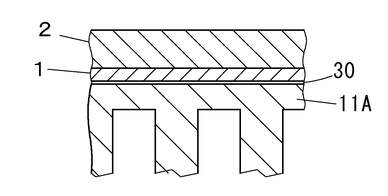
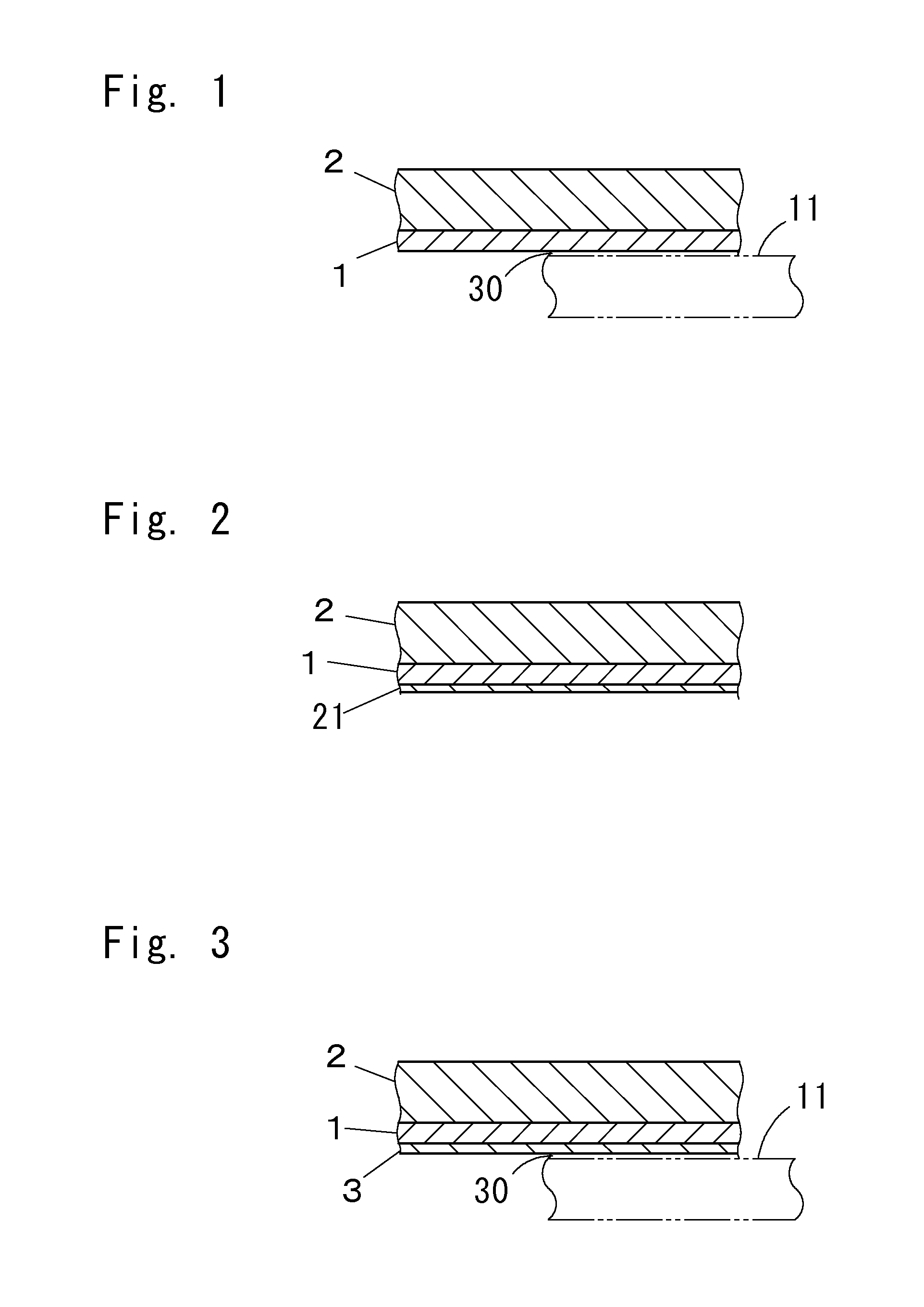
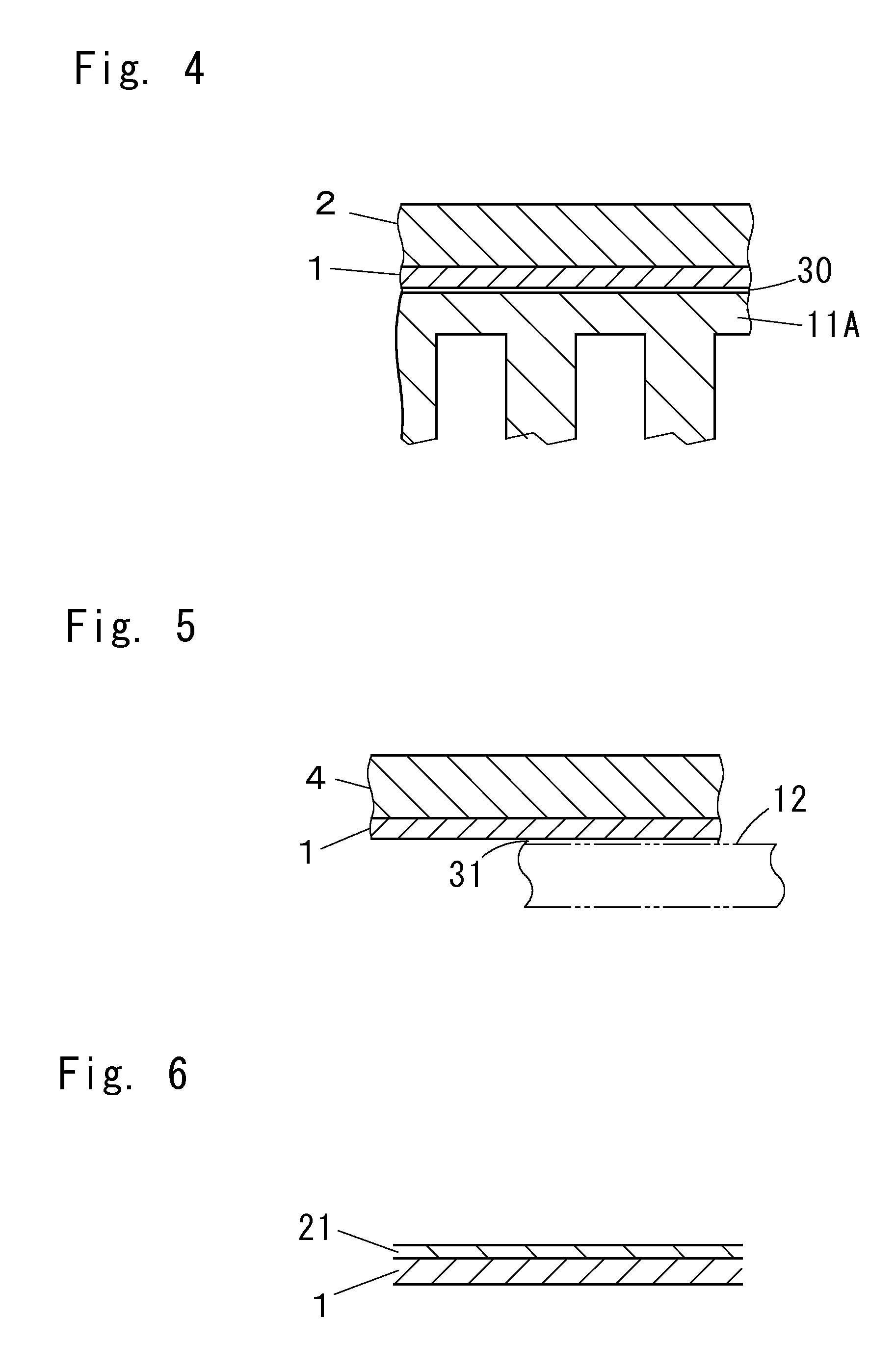
The patent describes a special aluminum alloy that can be easily welded, diffusion bonded, and brazed not just to other non-aluminum metals like steel, copper, nickel, and titanium, but also to pure aluminum. Additionally, the patent explains how to create a clad material and an aluminum bonding composite material that have a layer made of this special alloy.

Problems solved by technology

On the other hand, an aluminum material (a single-layer material) made of only aluminum is inferior in mechanical strength and corrosion resistance, and therefore a clad material is also often used that includes an aluminum layer made of aluminum and a non-aluminum metal layer made of stainless steel or nickel, with the layers being bonded together by pressure welding and diffusion bonding.
When these intermetallic compounds excessively grow, the bondability is significantly degraded.
Accordingly, the problem arises of impairing the bonding strength which is present before the brazing between the aluminum layer and the nickel layer in the heat-diffusion facilitating layer, or the aluminum layer and the iron layer due to the brazing.
However, it is difficult to bond the steel material and the aluminum material together by welding or brazing, and under current circumstances, these materials are mainly coupled with a mechanical coupling means such as rivets, and bolts and nuts.
Hence, it is necessary to decrease the degree of freedom in the designing and reduction of the productivity for an aluminum coupling composite material manufactured by coupling the steel material and the aluminum material together.

Method used


Image

  • Aluminum bonding alloy, and clad material and aluminum bonding composite material each having bonding alloy layer made of the alloy
  • Aluminum bonding alloy, and clad material and aluminum bonding composite material each having bonding alloy layer made of the alloy
  • Aluminum bonding alloy, and clad material and aluminum bonding composite material each having bonding alloy layer made of the alloy

Examples


example 1

(1) Manufacture of Aluminum Boding Alloy

[0070]Pure Ni (Mg=0%) and Ni—Mg-alloys with various amounts of Mg were melted to produce ingots as shown in Table 1. Each ingot (32 mm in thickness) was hot-rolled at 1000° C. for a hot-rolled plate (8 mm in thickness). The hot-rolled plate was cold-rolled (through five passes) into a cold-rolled plate (2 mm in thickness and 30 mm in width). During the rolling, the processing state of the plate was observed, and the result is shown in Table 1. In Table 1, the following symbols each indicate evaluation of the workability: “xx” indicates the case where the rolled plate was broken in the stage of the hot rolling, “x” indicates the case where the rolled plate was substantially broken in the stage of the cold rolling, “Δ” indicates the case where minute cracks each equal to or smaller than about 5 mm were generated in the side edge portions of the rolled plate in the stage of the cold rolling, and “∘” indicates the case where no crack was generated...

example 2

(1) Manufacture of Brazing Composite Materials

[0076]The pure-Ni plate (2 mm in thickness) of Alloy No. 1 and the alloy plates (each 2 mm in thickness) of Alloys Nos. 4 to 6, which were manufactured in the Example 1, were each cold-rolled into a bonding alloy plate having a plate thickness of 1 mm. A test piece (10 mm in width and 50 mm in length) for brazing was collected each from the bonding alloy plates. On the other hand, as shown in Table 3, metal plates each having a plate thickness of 1 mm, which were made of pure Al, pure Cu, SUS304 (a stainless steel), or SPCC (cold-rolled steel plate), were prepared as counterpart metal plates, and test pieces each having the same width were collected from the metal plates. As shown in FIG. 8, a test piece 51 formed from the bonding alloy plate and a test piece 52 formed from the counterpart metal plate were each folded into an L-shape such that the brazing length D was 10 mm. A thin plate (0.5 mm in thickness) 53 made of the brazing mater...


PUM

PropertyMeasurementUnit
mass %aaaaaaaaaa
mass %aaaaaaaaaa
temperatureaaaaaaaaaa

Abstract

An aluminum bonding alloy is an Ni—Mg alloy for bonding aluminum and a non-aluminum metal selected from steel, copper, nickel or titanium. The Ni—Mg alloy consists essentially of 0.08-0.90 mass % Mg, and the balance of Ni and inevitable impurities. A clad material includes a non-aluminum metal layer made of the non-aluminum metal and a bonding alloy layer made of the aluminum bonding alloy. The non-aluminum metal layer and the bonding alloy layer are bonded together by pressure welding and diffusion bonding.

Description

BACKGROUND OF THE INVENTION[0001]1. Field of the Invention[0002]The present invention relates to an aluminum bonding alloy excellent in pressure weldability, diffusion bondability and brazability not only to a non-aluminum metals such as steel, copper, nickel or titanium but also to aluminum, and a clad material and an aluminum bonding composite material each including a bonding alloy layer made of the bonding alloy.[0003]2. Description of the Related Art[0004]Aluminum is excellent in electric conductivity, workability and lightness, and therefore is used in many fields as a raw material of electrode materials, terminal materials, electrically conductive wire materials, etc. On the other hand, an aluminum material (a single-layer material) made of only aluminum is inferior in mechanical strength and corrosion resistance, and therefore a clad material is also often used that includes an aluminum layer made of aluminum and a non-aluminum metal layer made of stainless steel or nickel, ...

Claims


Application Information

Patent Timeline
Patent Type & Authority Patents(United States)
IPC IPC(8): B32B15/20B32B15/01B23K1/19B23K20/02B23K20/16B23K20/227B23K20/233B23K35/00B23K35/02B23K35/30C22C19/00C22C19/03
CPCB23K1/19B23K20/023B23K20/16B23K20/2275B23K20/2333B23K20/2336B23K35/002B23K35/004B23K35/0233B23K35/3033B32B15/015B32B15/017C22C19/007C22C19/03B23K2201/40B23K2203/10B23K2203/18B23K2203/20B23K2101/40B23K2103/10B23K2103/12B23K2103/14B23K2103/18B23K2103/20B23K2103/26Y10T428/12743Y10T428/1275Y10T428/12757Y10T428/12764Y10T428/12806Y10T428/1291Y10T428/12937B23K20/00B23K35/30
Inventor YAMAMOTO, SHINJIISHIO, MASAAKI
Owner NEOMAX MATERIALS
Learn More