
Multilayered tissue phantoms, fabrication methods, and use

a tissue phantom and multi-layered technology, applied in the field of biomedical applications, can solve the problems of limiting some uses of phantoms, hard matrices, and lack of mechanical properties similar to soft tissues, and achieve the effects of less expense, efficient use, and reproducing geometrical deformation

Inactive Publication Date: 2014-11-18
NAT RES COUNCIL OF CANADA
View PDF19 Cites 50 Cited by
  • Summary
  • Abstract
  • Description
  • Claims
  • Application Information

AI Technical Summary

Benefits of technology

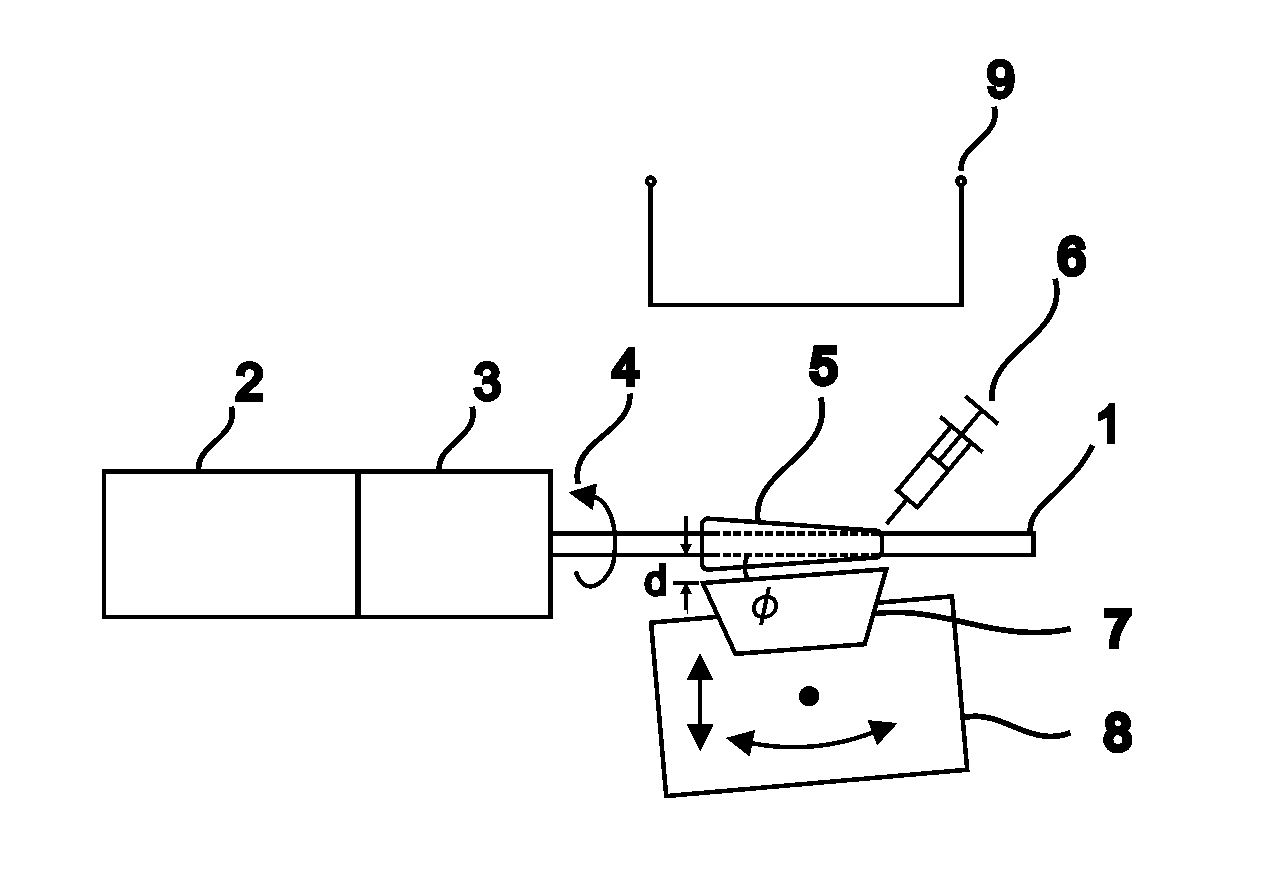
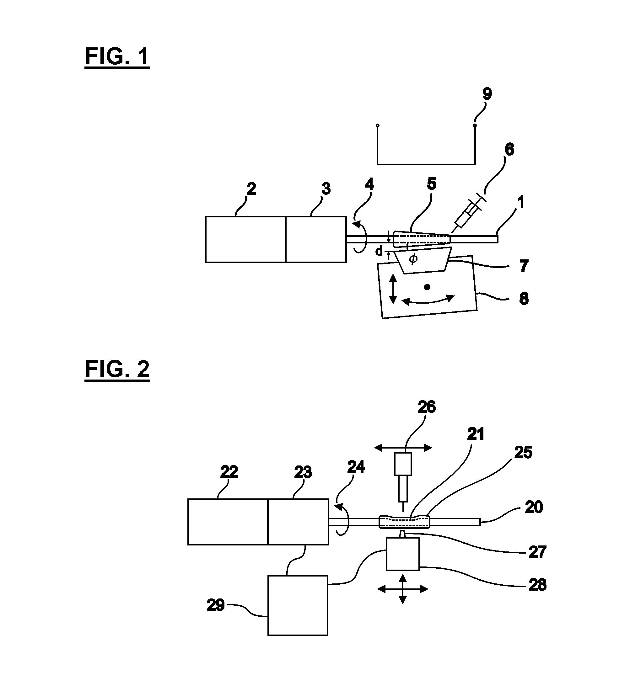
[0012]In accordance with the present invention a method is provided for fabrication of tissue-like phantoms that represent animal tissues and organs containing lumens, with tissue details like multiple layers. Each layer of the phantom has independently controlled optical properties that mimic the optical / infrared response of the targeted tissue layers. The layers may have controlled mechanical properties to mimic the behavior of the tissue. The first layer of a phantom is created by the application of the layer material on a supporting element, which effectively forms the lumen of the phantom. Subsequent layers are formed on top of previous layers, generally while the first layer is supported by the supporting element. The forming of the layer involves depositing a viscous flowable material and, before it completely solidifies, selectively redistributing the material to control a thickness distribution of the layer. A desired thickness distribution of the layer is preferably obtained by relative rotational motion between the supporting element and a wiper which contacts the material. The wiper may substantially remove material (e.g. if it is sharp and meets the material at a steep angle), or may substantially only spread the material (e.g. if it is dull or meets the material at a shallow angle), and may both spread and remove material at any given point in time.
[0017]In certain embodiments, the phantoms can also have other solid structures integrated to mimic pathologies, etc. The structures can be added during or after the process of the layer formation. They can be internal or external to the layers. The structures can be solid, liquid or gaseous. In the case of a liquid or gas, a void can be created by first adding a temporary material, crafting the phantom, removing the temporary material, and then filling the void with the desired product. In addition, phantoms can be attached (welded, glued, fused, stitched, etc.) together to create more complex structures.
[0025]For example, an OCT device operated at a typical wavelength of 1300 nm can not see through blood. The blood is therefore displaced temporarily and generally replaced by a liquid transparent at 1300 nm such as a saline solution. The liquid may be inside a compliant balloon and the probe is used inside the balloon that must be inflated to the dimension of the artery. Another approach consists in injecting the saline solution directly into the artery. If the volume is large enough, over a short period of time the blood would be almost entirely replaced by the saline. The OCT probe can be used efficiently during a few seconds. The flushing procedure may be initially developed using a phantom. The OCT probe would be used to quantify the effectiveness of the method.
[0027]The phantoms may mimic mechanical properties of tissue structures sufficiently to permit surgeons to learn how to operate on the tissues with the phantoms. Concurrently the phantoms can be used with new or old tools, devices, implants etc. and can teach the user how to use the same, with or without the functions of the imaging system. A surgeon may train on the phantom to use an imaging device and 3D volume visualization software to find pathological features, like obstructing plaques in arteries. Phantoms can be produced, stored, and disposed of, far more effectively and at less expense than an animal, or human cadaver tissues, especially given ethical considerations. Additionally necrotic tissue has properties that are difficult or expensive to reproduce in order to mimic living tissue. Abnormal tissues that are not very common can be reproduced using phantoms, once characterized making it easier to train someone to identify a larger set of possible tissue conditions.

Problems solved by technology

A housing is sometimes used to increase durability but can be inconvenient in use because such housings are known to influence measurements (U.S. Pat. No. 6,675,035 to Grable et al.).
However, these matrices are hard and do not provide mechanical properties similar to soft tissues.
This limits some uses of phantoms, for example in training surgeons on operations, as haptic and tactile responses are not similar, especially for procedures like endoscopy.
Furthermore molding of very thin layers, less than about 25 μm for example, can be exceedingly difficult, generally requires high pressure (which can damage other delicately formed features) and is prone to failure.
While highly planar features can be readily provided, even between layers of a phantom, by application of paint or powder prior to a subsequent overmolding step, the embedding of solid objects within a mold can be exceedingly difficult.
A general failure to provide precise localization of the object within a mold and numerous defects are recurring problems with solid objects in molds.
These problems may be exacerbated by subsequent overmolding steps.
Finally it is very difficult to produce very uniform thickness layers, or to provide a very high measure of control of thickness as a function of position of the layer, unless the phantom is molded.
With multilayered structures, the costs and tolerances of many molds that fit inside one-another is prohibitive for many applications.

Method used


Image

  • Multilayered tissue phantoms, fabrication methods, and use
  • Multilayered tissue phantoms, fabrication methods, and use
  • Multilayered tissue phantoms, fabrication methods, and use

Examples


example

Blood Vessel Embodiment

[0147]In one embodiment, the method we provide is used to produce blood vessel phantoms to be measured with OCT systems. Both types of blood vessels, arteries and veins, are tubular organs composed of three distinct tissue layers: the intima, the media, and the adventitia.

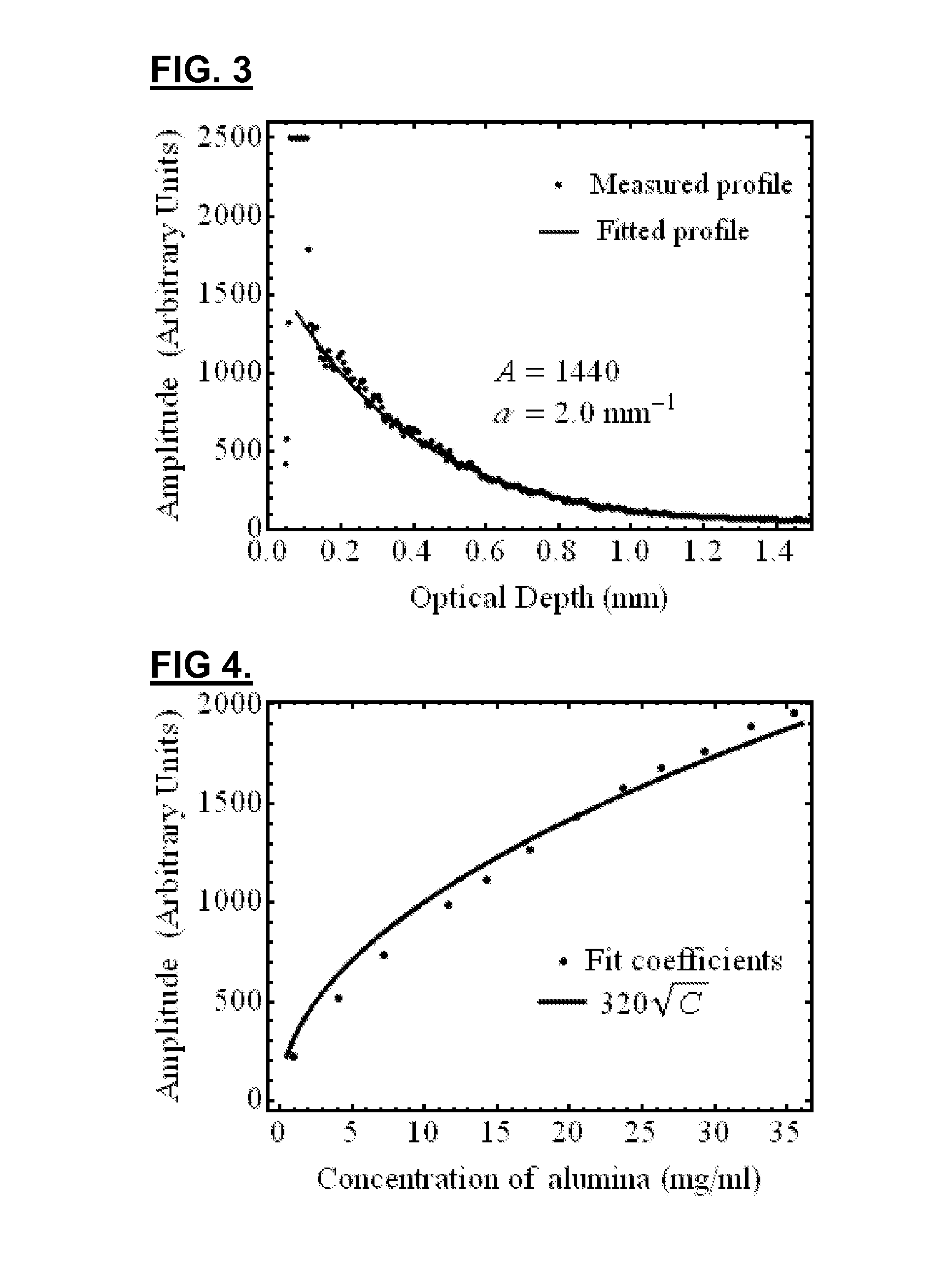
[0148]In this embodiment, the layer materials are mixtures of powders in silicone. In order to mimic the mechanical properties, the silicone is a mixture of Sylgard 184 and PDMS. The required OCT backscattered amplitude for each layer is mainly provided by alumina powder. The optical attenuation is adjusted with carbon black as required. With such compositions, the blood vessel phantoms are durable over many years and are highly resistant.

[0149]The ratio of PDMS:Sylgard resin:Sylgard reactive to approximate the elasticity of the targeted tissue was determined experimentally. In this case, the mechanical behavior of a coronary artery is reproduced as a whole instead of for each layer separatel...


PUM


Abstract

A method for producing a multilayer tissue phantom involves successively forming at least two layers, each layer formed by depositing a viscous flowable material over a supporting element or over a previously formed layer of the phantom supported by the supporting element, selectively redistributing the material while material is solidifying to control a thickness distribution of the layer, and allowing the material to solidify sufficiently to apply a next layer. The supporting element supports the material in 2 or 3 directions and effectively molds a lumen of the tissue. The neighboring layers are of different composition and of chosen thickness to provide desired optical properties and mechanical properties of the phantom. The phantom may have selected attenuation and backscattering properties to mimic tissues for optical coherence tomography imaging.

Description

[0001]This application claims the benefit of U.S. Provisional Patent Application Ser. No. 61 / 213,377 filed Jun. 2, 2009, the entire contents of which are herein incorporated by reference.FIELD OF THE INVENTION[0002]The present invention relates in general to phantoms for biomedical applications, their fabrication and their use, more specifically, the invention relates to phantoms targeting endoscopic applications of biomedical optics, including optical techniques that characterize the detailed structure of tissues as a function of depth.BACKGROUND OF THE INVENTION[0003]An optical phantom is a fabricated sample that provides an optical response similar to biological tissues for examination by one or more optical imaging system. In many cases, the interaction of electromagnetic (EM) radiation (herein “light”) with a tissue is described by the scattering and the absorption processes. In a scattering process, light is essentially redirected in a different direction. In the absorption pr...

Claims


Application Information

Patent Timeline
Patent Type & Authority Patents(United States)
IPC IPC(8): G09B23/30A61B5/00G09B23/28
CPCG09B23/285A61B5/00A61B2560/0228A61B2560/0233G01N2201/08G01N21/4785G01N2201/127G01N21/59G09B23/286
Inventor BISAILLON, CHARLES-ETIENNELAMOUCHE, GUYDUFOUR, MARC L.
Owner NAT RES COUNCIL OF CANADA
Learn More