Method for producing synthetic quartz glass

a technology of synthetic quartz glass and quartz glass, which is applied in the direction of glass deposition burners, manufacturing tools, instruments, etc., can solve the problems of high cost of flue gas scrubbing and disposal, and high cost of hydrochloric acid scrubbing and disposal. , to achieve the effect of reducing the cost of d4 purification and reducing the cost of d4, the process is time-consuming and expensiv

Active Publication Date: 2015-03-10
HERAEUS QUARZGLAS
View PDF101 Cites 1 Cited by
  • Summary
  • Abstract
  • Description
  • Claims
  • Application Information

AI Technical Summary

Benefits of technology

[0042]This effect can be ascribed to the fact that the broadening of the size distribution of the formed and depositing SiO2 particles either leads to a more homogeneous deposition of the SiO2 soot than in monodisperse SiO2 particles or that it facilitates a more uniform densification of the SiO2 soot during soot body production or during vitrification.
[0099]The method according to the invention is therefore particularly well suited for producing synthetic quartz glass that is used for the production of optical fibers. Small density variations of the soot body facilitate the production of high-quality quartz glass that is particularly suited for optical fibers for telecommunications.

Problems solved by technology

These methods are efficient, but time-consuming and cost-intensive.
On the other hand, hydrochloric acid which causes high costs in terms of flue gas scrubbing and disposal is formed during the reaction of SiCl4 and other chlorine-containing feedstock materials.
However, on account of the relatively high boiling temperature and the chemical similarity with other polyalkylcyclosiloxanes, such as hexamethylcyclotrisiloxane (D3), decamethylcyclopentasiloxane (D5), dodecamethylcyclohexasiloxane (D6) and tetradecamethylcycloheptasiloxane (D7), the purification of D4 requires a time-consuming and expensive distillation procedure.
It is reported that agglomerates of such high-boiling impurities lead to clogging in the gas supply system and effect “gel formation”, thereby producing defects in the quartz glass.
The defect mechanism seems here to be the deposition of undecomposed or incompletely decomposed high-boiling agglomerates that will subsequently decompose with release of gases and may lead to bubbles in the quartz glass.
The suggested two-step purifying method is complicated and expensive, and it has been found that, even in the case of an optimized process control, material inhomogeneities arise particularly in the form of thin layers of increased density in the quartz glass.
However, even at a constant liquid level, impurities of a relatively higher boiling point may gradually enrich in the liquid phase with formation of a “sump”, so that the composition of the feedstock material arriving at the deposition burner will change over time.
An additional problem will arise in soot deposition methods in which several consumers have to be simultaneously fed with the feedstock material, e.g. in the case of a soot deposition with a multiple burner assembly.
This, however, requires a complicated infrastructure of the media supply.
Yield and throughput are however comparatively low.
In the area of layers of increased density, this is only possible to a limited degree.
The reason is that the layers represent diffusion barriers which may produce a non-uniform treatment result in drying or sintering processes.
These problems arise because of long diffusion paths, especially with large-volume SiO2 soot bodies.
These inhomogeneities in the material of the soot body manifest themselves in the quartz glass body made therefrom, e.g. in the form of axial, radial or azimuthal variations of the hydroxyl-group or chlorine concentration or the viscosity values, and lead to unfavorable properties in the end product, such as e.g. an unfavorable damaging behavior with respect to radiation with high-energy UV light.

Method used


Image

  • Method for producing synthetic quartz glass
  • Method for producing synthetic quartz glass
  • Method for producing synthetic quartz glass

Examples


Embodiment Construction

[0100]The invention will now be explained in more detail with reference to embodiments and a drawing, in which:

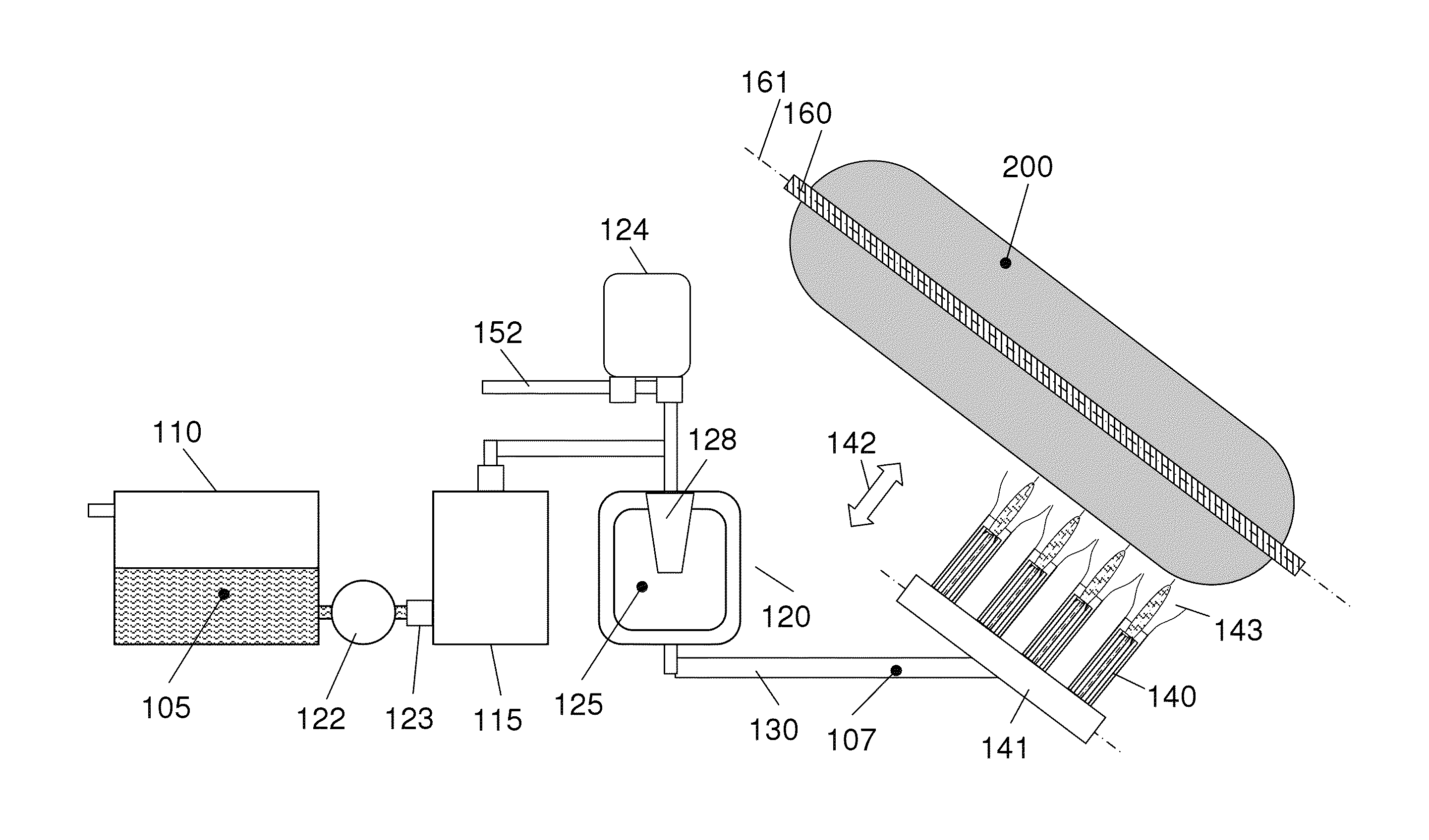
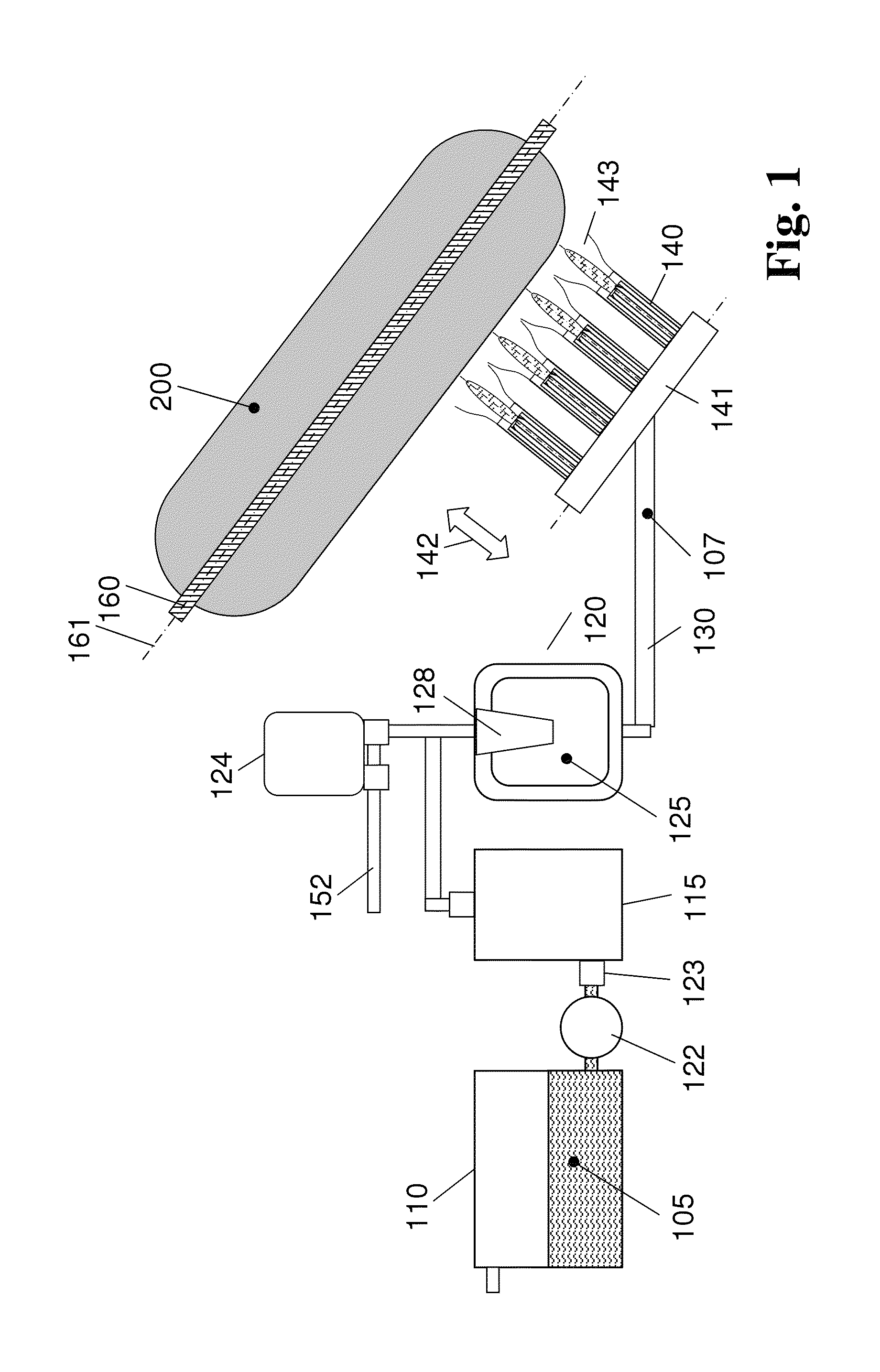
[0101]FIG. 1 shows a device for performing the method according to the invention for producing a SiO2 soot body, in a schematic illustration;

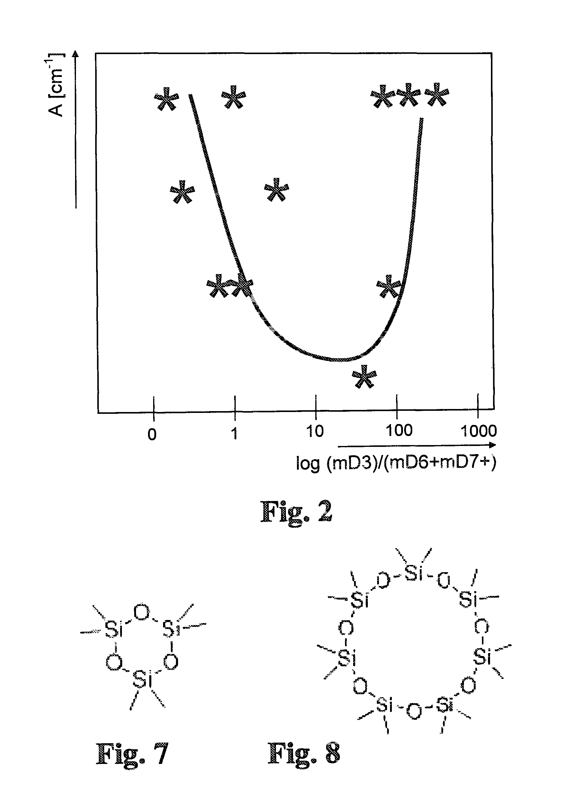
[0102]FIG. 2 shows a diagram regarding the layer density in soot bodies in dependence upon the composition of the feedstock material;

[0103]FIG. 3 is a CT image of a soot tube produced according to the invention from different polyalkylsiloxanes using a feedstock material, in a view taken in the direction of the longitudinal axis of the soot tube;

[0104]FIG. 4 shows, by way of comparison, a CT image of a SiO2 soot tube produced as feedstock material on the basis of the prior art by using a pure octamethylcyclotetrasiloxane;

[0105]FIG. 5 is a schematic diagram showing the various elements of the quartz-glass producing system according to the invention;

[0106]FIG. 6 is a schematic illustration of a vaporization chamber;

[0107]FIG. 7 shows a c...


PUM

PropertyMeasurementUnit
weight ratioaaaaaaaaaa
mean diameteraaaaaaaaaa

Abstract

A method for producing synthetic quartz glass comprises providing a liquid SiO2 feedstock material containing mainly octamethylcyclotetrasiloxane D4, vaporizing the SiO2 feedstock material into a feedstock vapor, converting the feedstock vapor into SiO2 particles, depositing the SiO2 particles on a deposition surface while forming a porous SiO2 soot body, and vitrifying the SiO2 soot body while forming the synthetic quartz glass. To produce large-volume cylindrical soot bodies with outer diameters of more than 300 mm of improved material homogeneity, the liquid feedstock material contains additional components comprising hexamethylcyclotrisiloxane D3 and its linear homolog with a weight fraction mD3, dodecamethylcyclohexasiloxane D6 and its linear homolog with a weight fraction mD6, and tetradecamethylcycloheptasiloxane D7 and / or hexadecamethylcyclooctasiloxane D8 and its linear homologs with a weight fraction mD7+. The weight ratio mD3 / mD6 is in a range between 0.5 and 500 and the weight fraction mD7+ is at least 20 wt. ppm.

Description

RELATED APPLICATIONS[0001]This application claims the benefit of U.S. provisional application Ser. No. 61 / 569,083 filed Dec. 9, 2011, which is herein incorporated in its entirety by reference.FIELD OF THE INVENTION[0002]The present invention relates to a method for producing synthetic quartz glass, the method comprising the steps of:[0003](a) providing a liquid SiO2 feedstock material, which contains octamethylcyclotetrasiloxane D4 as the main component,[0004](b) vaporizing the SiO2 feedstock material into a feedstock material vapor,[0005](c) converting the feedstock material vapor into SiO2 particles,[0006](d) depositing the SiO2 particles on a deposition surface while forming a porous SiO2 soot body,[0007](e) vitrifying the SiO2 soot body while forming the synthetic quartz glass.PRIOR ART[0008]For the production of synthetic quartz glass for commercial applications, SiO2 particles are produced from a silicon-containing start substance in a CVD method (chemical gas phase deposition...

Claims


Application Information

Patent Timeline
Patent Type & Authority Patents(United States)
IPC IPC(8): C03B37/018C03B19/14C03B37/014
CPCC03B37/018C03B37/01413C03B19/1415C03B2207/32C03B2207/85C03B19/14C03B37/014
Inventor FABIAN, HEINZROEPER, JUERGEN
Owner HERAEUS QUARZGLAS
Why Eureka
Try Eureka