Particle image velocimetry suitable for X-ray projection imaging

a particle image and x-ray technology, applied in the field of x-ray projection imaging, can solve the problems of poor spatial and temporal resolution, limit the application of in vivo flow analysis techniques to piv techniques using visible light, and limit the scope of optically transparent samples

Active Publication Date: 2015-05-19
4DX LTD
View PDF7 Cites 22 Cited by
  • Summary
  • Abstract
  • Description
  • Claims
  • Application Information

AI Technical Summary

Benefits of technology

The present invention provides a new method for X-ray imaging that can perform early detection and diagnosis of diseases or disorders, as well as provide valuable information in industry and laboratories. Compared to traditional CT, the method can measure 3D motion fields in opaque samples and has a short scan time, minimizing sample exposure to the radiation source. Overall, this method has the ability to decode far more information from an image and offers improved functionality in X-ray imaging.

Problems solved by technology

Currently available techniques for flow field measurement in opaque vessels, such as magnetic resonance imaging based techniques, suffer from poor spatial and temporal resolution, limiting the application of these techniques for in vivo flow analysis.
PIV techniques using visible light are limited to optically transparent sample.
These algorithms assume pulsed (instantaneous) illumination and zero out-of-plane, flow gradients and therefore fail to take into account the 3D characteristics of imaging real flows using X-rays.
This results in a significant under estimation of flow velocity.
Single projection images are insufficient for evaluating three components of velocity.
CT has the advantage of offering the best resolution and penetration of all medical imaging modalities, but also has the significant disadvantage of delivering high doses of X-rays.
But even though they offer the best resolution and penetration of all medical imaging modalities, the X-ray PIV techniques of the prior art use particle images taken at a single viewing angle, which contain no particle displacement information in the direction parallel to the X-ray beam, and therefore they suffer the drawback that they are limited to two component velocity measurements.
Also, no information regarding the velocity profile in the dimension perpendicular to the image plane is available, and therefore 3D measurements are not possible without prior knowledge of the flow.

Method used


Image

  • Particle image velocimetry suitable for X-ray projection imaging
  • Particle image velocimetry suitable for X-ray projection imaging
  • Particle image velocimetry suitable for X-ray projection imaging

Examples


example 1

[0198]In this example the method of the present invention has been applied to the measurement of a strongly 3D flow.

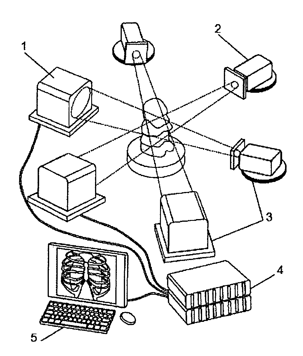
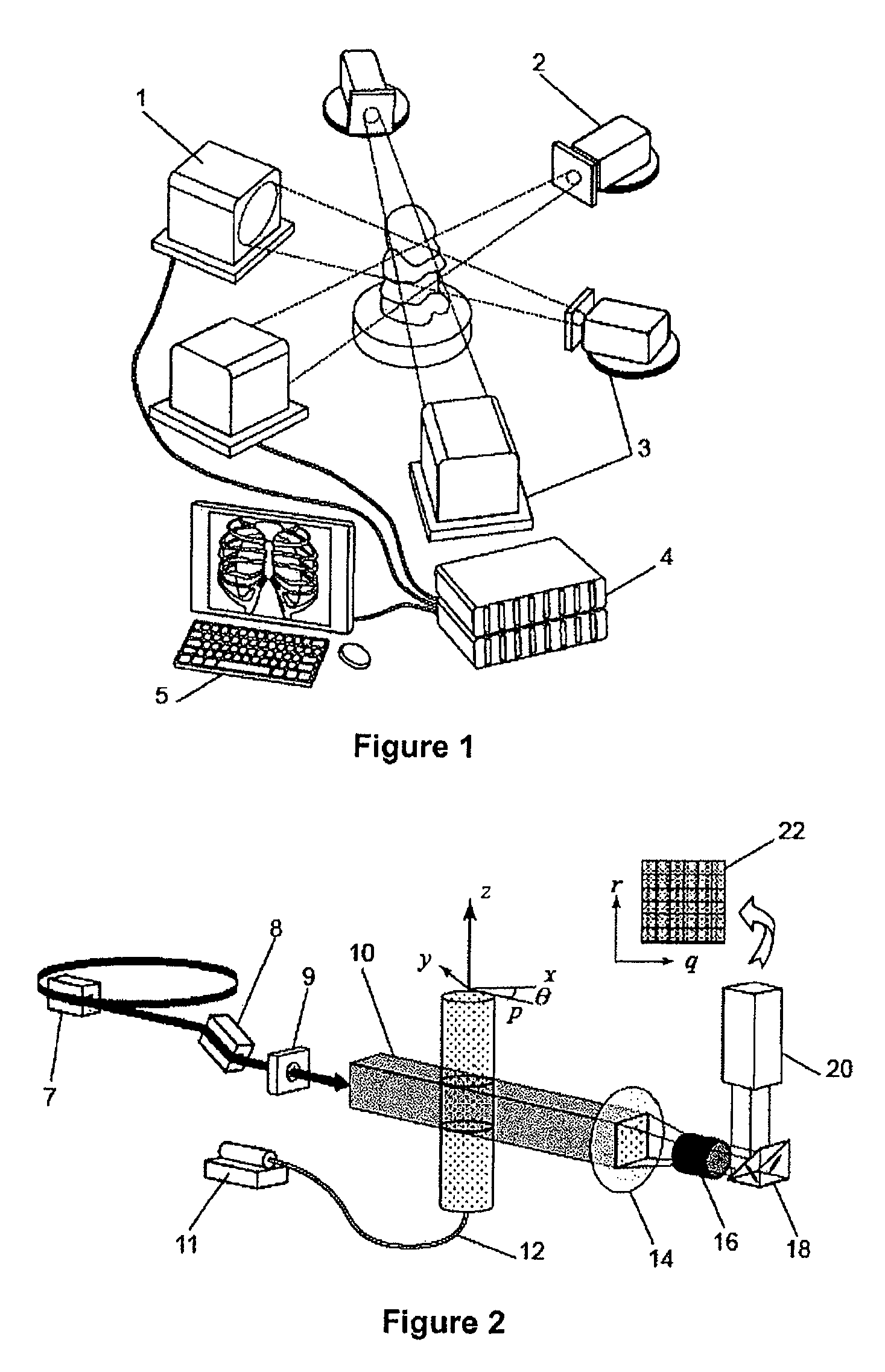
[0199]The relevant imaging setup is shown in FIG. 1. The monochromatic beam in this case passes through a particle-seeded fluid (hollow glass spheres in glycerine). X-rays are slightly refracted at the interfaces between materials. The transmitted and refracted rays are allowed to propagate and interfere before being co-converted into visible light by the scintillator. This is then imaged using a high-speed detector and visible light optics, resulting in a phase contrast projection image. The image results from the superposition of interference fringes generated by the particle-liquid interfaces creating a dynamic speckle pattern that faithfully follows the particles.

[0200]Unlike visible light based imaging systems, in which images contain focus or holographic information from which depth can be inferred, the transmission nature of CTXV results in 2D volumetric project...

example 2

[0208]In this example experiments are described which demonstrate the application of CTXV to the simultaneous measurement of structure and velocity The method of the present invention was used with a high resolution medical imaging beam-line (BL20XU) on a Spring-8 synchrotron at Hyogo, Japan set up as shown in FIG. 2. The source to sample distance of 245 meters provides highly coherent X-rays for phase contrast imaging. A Si-111 double crystal monochromator was used to provide a monochromatic beam energy of 25 KeV.

Sample

[0209]The sample comprised an optically opaque plastic arterial model, with an average diameter of 950 μm, manufactured using a 3D-printing technology. The model was manufactured out of the Objet™ FullCure® acrylic-based photopolymer material. The high resolution technique, with a layer thickness of 16 μm, ensured the models were accurate on the small scale being investigated. The geometry was chosen to mimic a stenosed artery; generating a three-dimensional flow fie...

example 3

[0216]In this example a further experiment is described which demonstrate the application of CTXV to the simultaneous measurement of structure and velocity. The method of the present invention is again used with a high resolution medical imaging beam-line (BL20XU) of the Spring-8 synchrotron at Hyogo, Japan.

Sample

[0217]The sample used was an opaque plastic model with a complex three-dimensional geometry (FIG. 7(a)), manufactured using Object rapid prototyping technology. The test section consisted of a solid cylinder of 14 mm diameter, with a hollow section allowing internal flow of the working fluid. The geometry of the hollow section was constructed as the union of a cone and a helically swept circle, resulting in corkscrew geometry with a decreasing cross-sectional area. The geometry was chosen to exhibit a strongly three-dimensional flow. The working fluid, glycerine seeded with 35 um (nominal) solid glass spheres was pumped through the model at 0.1 ml / min using a syringe pump. ...


PUM


Abstract

A 2D or 3D velocity field is reconstructed from a cross-correlation analysis of image pairs of a sample, without first reconstructing images of the sample spatial structure. The method can be implemented via computer tomographic X-ray particle image velocimetry, using multiple projection angles, with phase contrast images forming dynamic speckle patterns. Estimated cross-correlations may be generated via convolution of a measured autocorrelation function with a velocity probability density function, and the velocity coefficients iteratively optimized to minimize the error between the estimated cross-correlations and the measured cross-correlations. The method may be applied to measure blood flow, and the motion of tissue and organs such as heart and lungs.

Description

CROSS REFERENCE TO RELATED APPLICATIONS[0001]This application is a National Stage of International Application No. PCT / AU2010 / 001199 filed Sep. 16, 2010, claiming priority based on Australian Patent Application No. 2009904481 filed Sep. 16, 2009, the contents of all of which are incorporated herein by reference in their entirety.FIELD OF INVENTION[0002]The present invention relates to imaging, particularly imaging of movement.[0003]In one aspect the present invention relates to the field of biomedical engineering, particularly in vivo or in vitro imaging.[0004]In another aspect, the invention relates to technology for imaging of function and form in a wide range of research, medical and industrial applications.[0005]In a yet further aspect the present invention is suitable for use as a method and device for imaging the movement of living tissue.[0006]It will be convenient to hereinafter describe the invention in relation to in vivo medical imaging, however it should be appreciated t...

Claims


Application Information

Patent Timeline
Patent Type & Authority Patents(United States)
IPC IPC(8): G06K9/00A61B6/00A61B5/08A61B6/03A61B8/08A61B5/087A61B8/06G06T7/00G06T7/20G01F1/712A61B5/026
CPCA61B6/4085G01F1/712G06T2207/30061A61B6/508A61B6/032A61B6/507A61B5/0261A61B6/484G06T2207/20112A61B6/482A61B6/5217A61B6/4007A61B6/504G06T2207/10124A61B5/087A61B5/08G06T7/20G06T7/0079A61B8/485A61B6/4092A61B8/06A61B6/4014G16H50/30
Inventor FOURAS, ANDREASDUBSKY, STEPHEN
Owner 4DX LTD
Why Eureka
Try Eureka