Systems and methods for advanced sanitary sewer infrastructure management

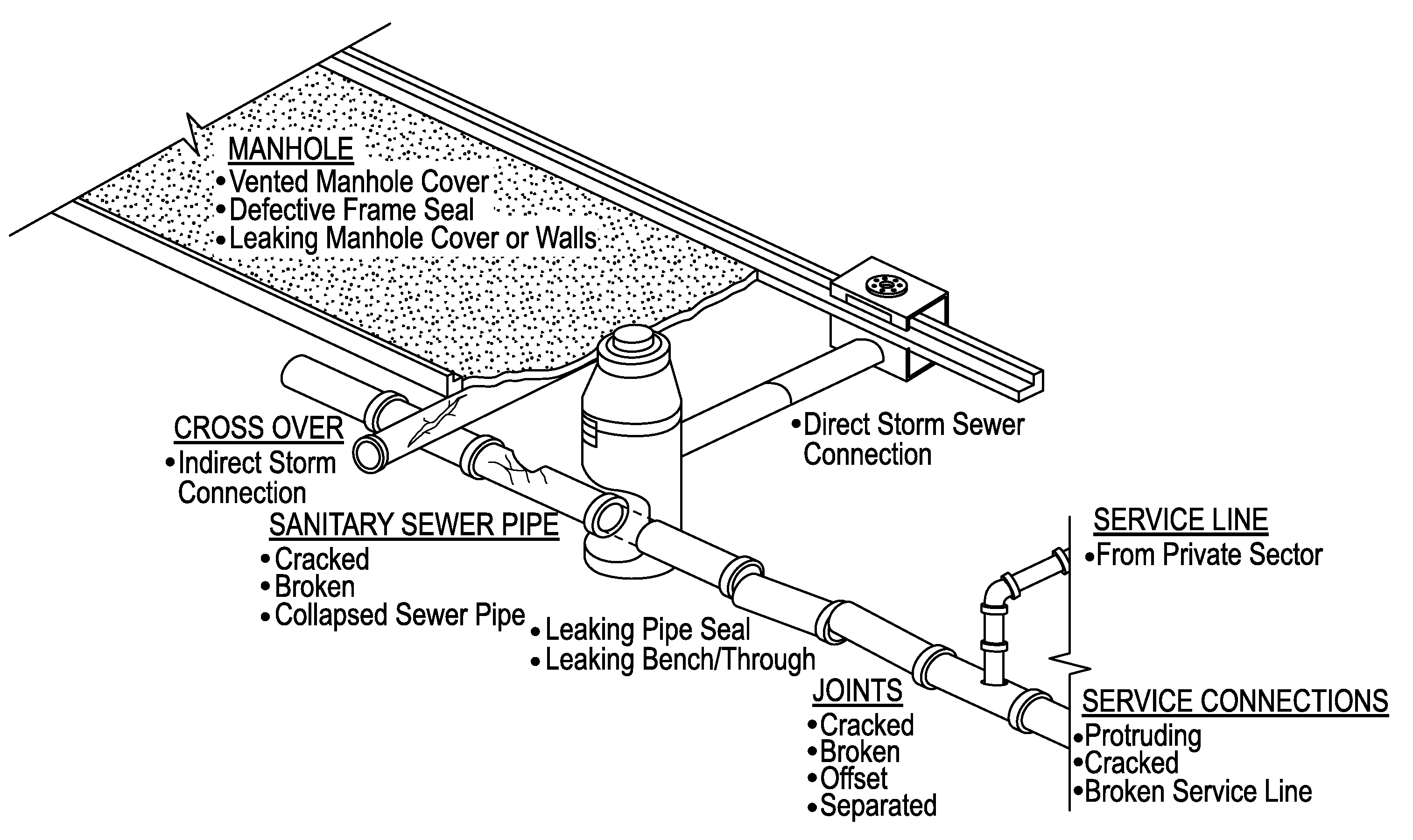
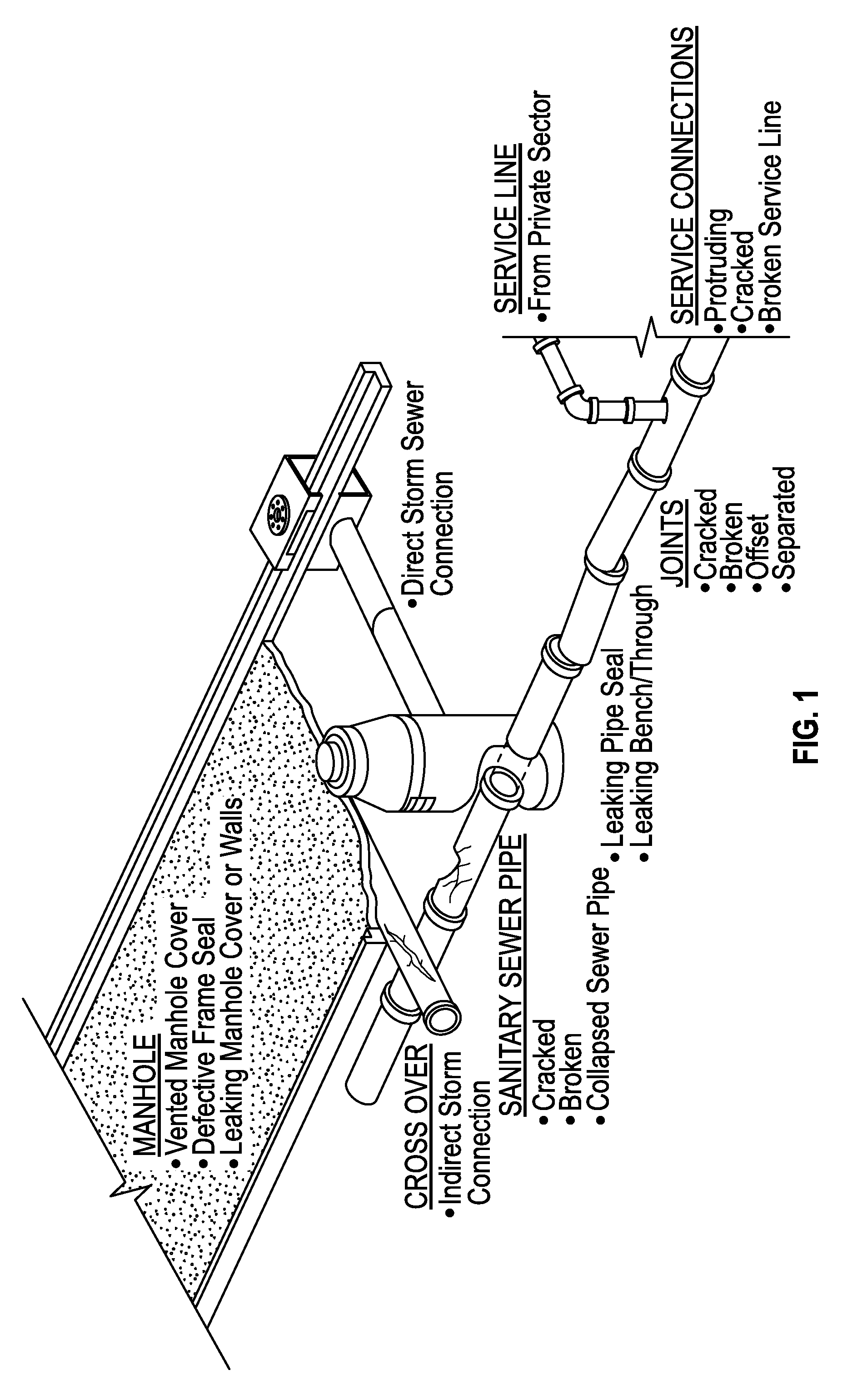
a technology infrastructure management, applied in the field of advanced sanitary sewer infrastructure management, can solve the problems of aging of the infrastructure itself, damage to manholes, cracking of pipes or joints between pipes, etc., and achieve the effect of saving significant time and efficient automation of workflows

Active Publication Date: 2015-07-14
T4 SPATIAL LLC
View PDF18 Cites 13 Cited by
  • Summary
  • Abstract
  • Description
  • Claims
  • Application Information

AI Technical Summary

Benefits of technology

[0022]Disclosed embodiments act as a “Rosetta Stone,” taking full advantage of the emerging geospatial paradigm for the first time in order to bring all the disparate and isolated information together in a synchronous whole with the purpose of efficiently automating workflows associated with advanced sanitary sewer infrastructure management. Embodiments may also use the highly visual nature of the geospatial paradigm to manage all the parts and lifecycles of sanitary sewer infrastructure management, realizing multiple synergistic benefits that are not available under current management practices. As a result, engineers and contractors can not only save significant time in accessing the full information necessary to do their jobs, and but also do their jobs to a degree of efficacy not otherwise possible.

Problems solved by technology

There are several key issues with sanitary sewer infrastructure management with which developed countries are currently grappling.
Primary among them is aging of the infrastructure itself.
Aging may crack pipes or the joints between the pipes, damage manhole structures along streets, or lead to a range of other problems.
Before 1950, sewer line pipe and joint materials were not as effective as those used today.
Many older pipes and joints are simply failing.
However, during rainstorms breaks in sewer pipes, cracks in joints, and, especially, the linking of storm water and sewer systems, allow storm water to mix in with the raw sewage, leading, in some cases, to multiples of the normal underlying sewage volume.
Money is wasted on treating storm water that simply should not be mixed in with the sewage.
It is well documented that larger waste water treatment plants can actually spend millions of dollars per year on the chemicals needed to treat these storm-related surges of flow.
In addition to overwhelming the waste water treatment plants and causing SSOs, the increased sewage flow during storms may also overwhelm the local pipes themselves.
This can result in sewage backups into nearby residents' or businesses' basements, as well as manholes that blow off and allow raw sewage to run across city streets and yards.
This increase of flow into sewers during rain storms is known as the “Infiltration and Inflow” (I / I) problem because it is due to the infiltration of rainwater into what should be a closed sewer system, but which is not, due to either cracking, leaking joints, and / or bad design.
There are two additional related issues that can exacerbate these I / I problems.
The first issue is tree roots.
Tree roots are very opportunistic.
Tree roots may also begin to grow inside the sewer pipes themselves, and over time can significantly block the design flow of the pipes.
The second issue that exacerbates I / I problems is the buildup of fats, oil, and grease (known as “FOG”) on the inside of sewer pipes.
During a storm event, these buildups block the design flow of the pipe.
Both of these issues may lead directly to basement sewage backups and / or to raw sewage spilling out of manholes.
Simultaneously, there has been less funding available to simply build bigger treatment plants or bigger holding tanks for temporary storm surge storage.
Building a much larger, very costly, treatment plant or holding tanks designed to handle multiples of the normal volume of sewage flow for storms that only occur a few times a year simply does not make good economic sense.
The first layer of the problem addressed by certain embodiments disclosed herein is that cities and communities have wide variance in their waste water system records—in the kind of information they track, the quality of that information, and the completeness of the information.
There are also difficulties in knowing precisely the accurate location of a particular asset, because many cities still are using mapping systems that predate Global Positioning System (GPS) technology.
CAD software is able to generate sophisticated engineering drawings, but traditionally such drawings do not have good database record structures.
Thus, the as-built or CAD drawings cannot be updated with repairs, changes, etc., because they lack the database structure to do so.
The way one city tracks its waste water assets may not at all match how another city tracks those same types of assets.
Additionally, the information tracked typically suffers from varying degrees of completeness, and frequently is not kept up-to-date in any standardized way.
Finally, the information tends to be confusing and to degenerate towards inaccuracy at a very basic level.
Conventional asset management software has not addressed these location issues effectively.
To date, these programs have tended to not be particularly strong on the asset detail record side and / or on the workflow coordination side.
In addition, for many of these programs, the geospatial locations of the assets have been derived from the original CAD drawings, which is very problematic.
In general, the accuracy of the geospatial coordinates for the involved assets cannot be relied on for damage prevention or advanced asset management practices.
However, they are inherently flawed in that they get increasingly inaccurate as one moves away from their foundational zero points.
These two-dimensional systems are not a match for the curved surface and actual three-dimensional terrain of the Earth.
This is at the core of why there can be such a mismatch between CAD drawings used for sewage (or other) infrastructure and physical reality.
So not only do the as-built drawings not match physical reality, but they frequently do not agree with each other.
On a practical level, for the engineers and workers in the field, this means that it can be extraordinarily difficult to see where other infrastructure (e.g., a gas distribution line or a fiber optic line) is in relationship to a sewer line or other sewer infrastructure, or to communicate precisely where a particular fault is located so that it can be evaluated and ultimately fixed.
In all cases, engineers and contractors typically spend substantial amounts of time trying to manually bring together all of the disparate and isolated information in order to get their jobs done.
As a result, engineers and contractors can not only save significant time in accessing the full information necessary to do their jobs, and but also do their jobs to a degree of efficacy not otherwise possible.

Method used


Image

  • Systems and methods for advanced sanitary sewer infrastructure management
  • Systems and methods for advanced sanitary sewer infrastructure management
  • Systems and methods for advanced sanitary sewer infrastructure management

Examples


example security

[0154 Model

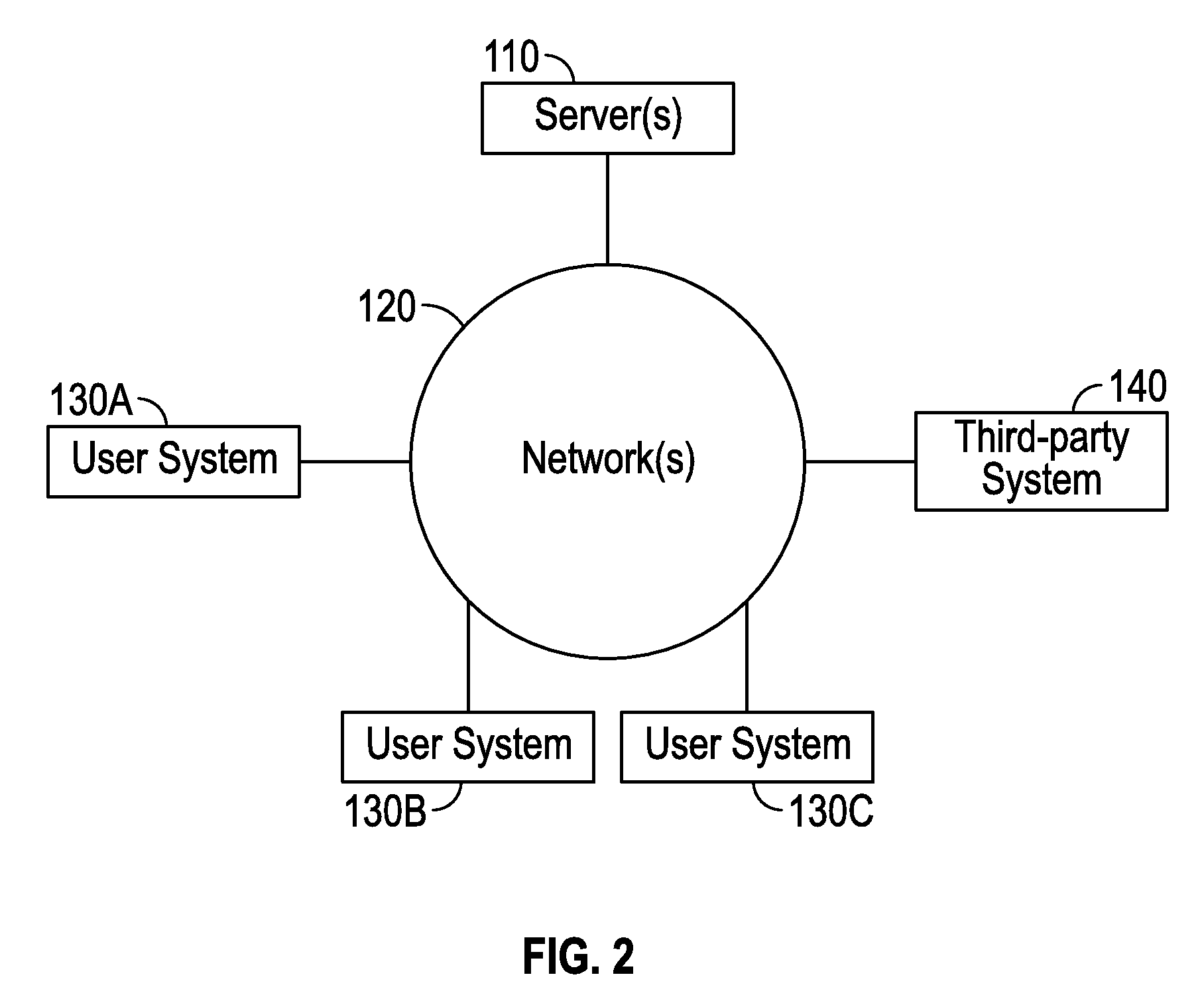
[0155]As mentioned above, server platform 110 may provide security for restricting access to certain data, modules, and / or functions. In an embodiment, server platform 110 implements three security tiers: access control, authorization, and permissions. A user is given access to platform 110, and is authorized to see certain data and use certain modules, and has one or more permissions to use certain functions. Server platform 110 may employ a central repository for user account information which is managed from an administration application. A central authentication system (CAS) server uses the central repository to authenticate users centrally to all the application environments supported by server platform 110.

[0156]When a user attempts to log in to an environment, the application negotiates a login with the CAS server and grants access to the user to one or more of the environments. During the authentication process, the application may also derive or retrieve other in...

example processing

[0173 Device

[0174]FIG. 16 is a block diagram illustrating an example wired or wireless system 550 that may be used in connection with various embodiments described herein. For example, system 550 may be used as or in conjunction with one or more of the mechanisms or processes described above, and may represent components of server platform 110, user system(s) 130, third-party system 140, data sources 142, 144, 146, 148, and / or other devices described herein. The system 550 can be a server or any conventional personal computer, or any other processor-enabled device that is capable of wired or wireless data communication. Other computer systems and / or architectures may be also used, as will be clear to those skilled in the art.

[0175]The system 550 preferably includes one or more processors, such as processor 560. Additional processors may be provided, such as an auxiliary processor to manage input / output, an auxiliary processor to perform floating point mathematical operations, a spec...


PUM


Abstract

Systems and methods for managing a sanitary sewer infrastructure. In an embodiment, a plurality of representations of infrastructure assets are re-projected from a plane coordinate system into a geospatial coordinate system, such that each of the re-projected plurality of representations of infrastructure assets is associated with a geospatial coordinate. Each of the re-projected plurality of representations of infrastructure assets and its associated geospatial coordinate is stored in one or more databases. Subsequently, geospatial coordinates, collected in the field, may be received from one or more user devices, wherein each geospatial coordinate corresponds to a geospatial location of an infrastructure asset. A stored geospatial coordinate associated with one or more of the stored re-projected plurality of representations of infrastructure assets may then be adjusted based on the received geospatial coordinates.

Description

BACKGROUND[0001]1. Field of the Invention[0002]The invention is generally directed to infrastructure management, and, more particularly, to advanced management of a sewer infrastructure.[0003]2. Description of the Related Art[0004]Good water infrastructure management is critical for communities all over the world—not only for quality-of-life reasons, but also for public health reasons. When discussing water infrastructure management, the topic is typically broken down into its three components—what engineers refer to as the “three waters”—drinking water, storm water, and sanitary sewer water (also known as waste water).[0005]There are several key issues with sanitary sewer infrastructure management with which developed countries are currently grappling. Primary among them is aging of the infrastructure itself. Aging may crack pipes or the joints between the pipes, damage manhole structures along streets, or lead to a range of other problems. It is not unusual in major cities for a l...

Claims


Application Information

Patent Timeline
Patent Type & Authority Patents(United States)
IPC IPC(8): G06F17/50G06Q50/26H04L29/08G06Q50/06G06F17/30
CPCG06F17/5004G06Q50/26H04L67/10G06F17/30241G06F2217/34G06Q50/06G06F30/13G06F2113/14G06Q10/0631G06Q50/08G06F16/29
Inventor CURRIN, DAVID BRETTEASTER, CLARKMARSH, BRENDANRICHARDS, II, EDMUND BENNETTCASTILLO AQUEVEQUE, ROGELLO FERNANDO
Owner T4 SPATIAL LLC
Why Eureka
Try Eureka