Treatment of nitrogen oxides in flue gas streams

a technology of flue gas stream and nitrogen oxide, which is applied in the direction of dispersed particle separation, chemistry apparatus and processes, and separation processes, etc., can solve the problems of brown plume, wet scrubbing desulfurization techniques used for so/sub>x /sub>removal of combustion flue gas, and the presence of pollutants in the combustion flue gas stream

Inactive Publication Date: 2015-08-25
EVONIK OPERATIONS GMBH
View PDF16 Cites 12 Cited by
  • Summary
  • Abstract
  • Description
  • Claims
  • Application Information

AI Technical Summary

Problems solved by technology

Combustion of fuels such as coal, coke, natural gas or oil typically results in the presence of pollutants in the combustion flue gas stream resulting from the combustion process or derived from impurities present in the fuel source.
Electric utility power plants that burn coal are a significant source of such combustion process air pollutants, but other stationary fuel-burning facilities such as industrial boilers, waste incinerators, and manufacturing plants are also pollution sources.
Such integrated air pollution control systems represent a particular challenge in situations requiring retrofitting of first-time or additional or enhanced pollution control measures, e.g., older coal-fired electric power plants without any desulfurization measures or power plants with SOX controls requiring modifications for control of NOX gas emissions.
The presence of NOX in a flue gas stream discharged to the atmosphere can result in a “brown plume” and is a contributor to ground-level ozone pollution (“smog”) and to acidifying nitrate deposition.
The wet scrubbing desulfurization techniques utilized for SOX removal from combustion flue gas are largely unsuccessful for removal of NO that is also present since the latter has low water solubility and is not amenable to aqueous alkali desulfurization scrubbing techniques.
Drawbacks to commercial SNCR systems are their requirement of very high and narrow temperature ranges to effect conversion of NOX to N, which often results in undesirable reaction byproducts, and their NOX removal rates of only 30-70%.
In actual commercial practice, the engineering challenge is the design of an integrated air pollution control system that can be retrofitted to existing fossil-fuel fired electric utility plants that are in need of updated or upgraded pollution controls for one or more of SO2, SO4, NO, NO2, Hg, HCl, HF, CO2 and particulates.

Method used


Image

  • Treatment of nitrogen oxides in flue gas streams
  • Treatment of nitrogen oxides in flue gas streams
  • Treatment of nitrogen oxides in flue gas streams

Examples


example 1

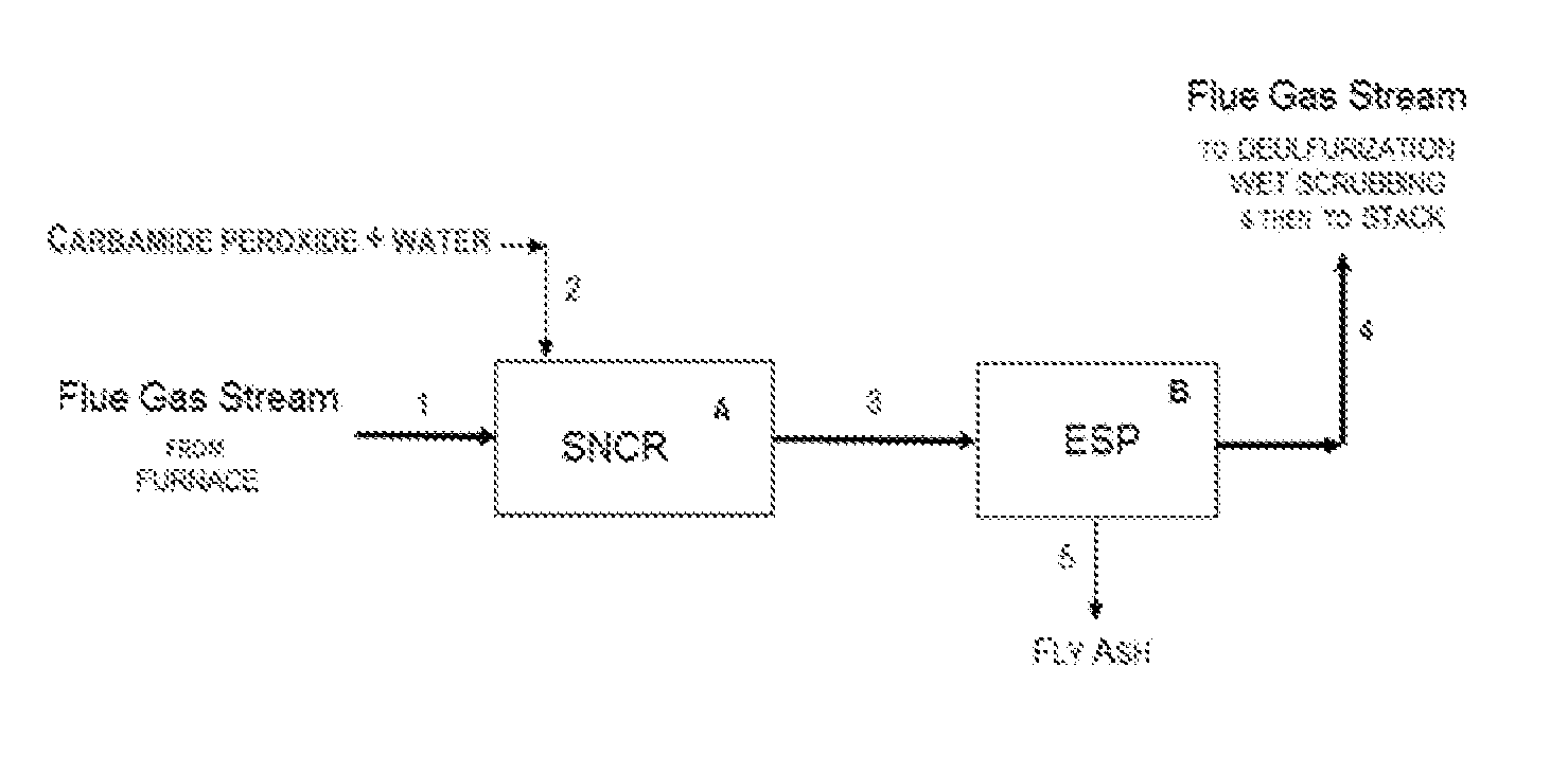
[0102]Examples 1-3 utilized the following laboratory apparatus. The lab set-up included a pre-heater consisting of a quartz tube heated by a Lindberg tube furnace; an insulated heated tube reactor (diameter: 10 mm, length: 1,200 mm); and auxiliary equipment including a syringe pump, temperature controllers, gas flow meters, gas distribution panel, cold trap, and mist catcher.

[0103]A gas mixture consisting of NO, O2, and N2 was introduced as a gas stream first into the pre-heater and then into the insulated heated tube reactor heated to a predetermined temperature. The gas components of the gas mixture were sourced from nitrogen gas, air, and NO in nitrogen (390 ppm NO in N2). Concentrations of each component in the gas mixture were adjusted by a flow rate meter.

[0104]An injection inlet was provided at a position at the entrance to (upstream of) the insulated heated tube reactor, and aqueous urea-H2O2 reagent solutions were injected into the flowing gas stream through a stainless ste...

example 2

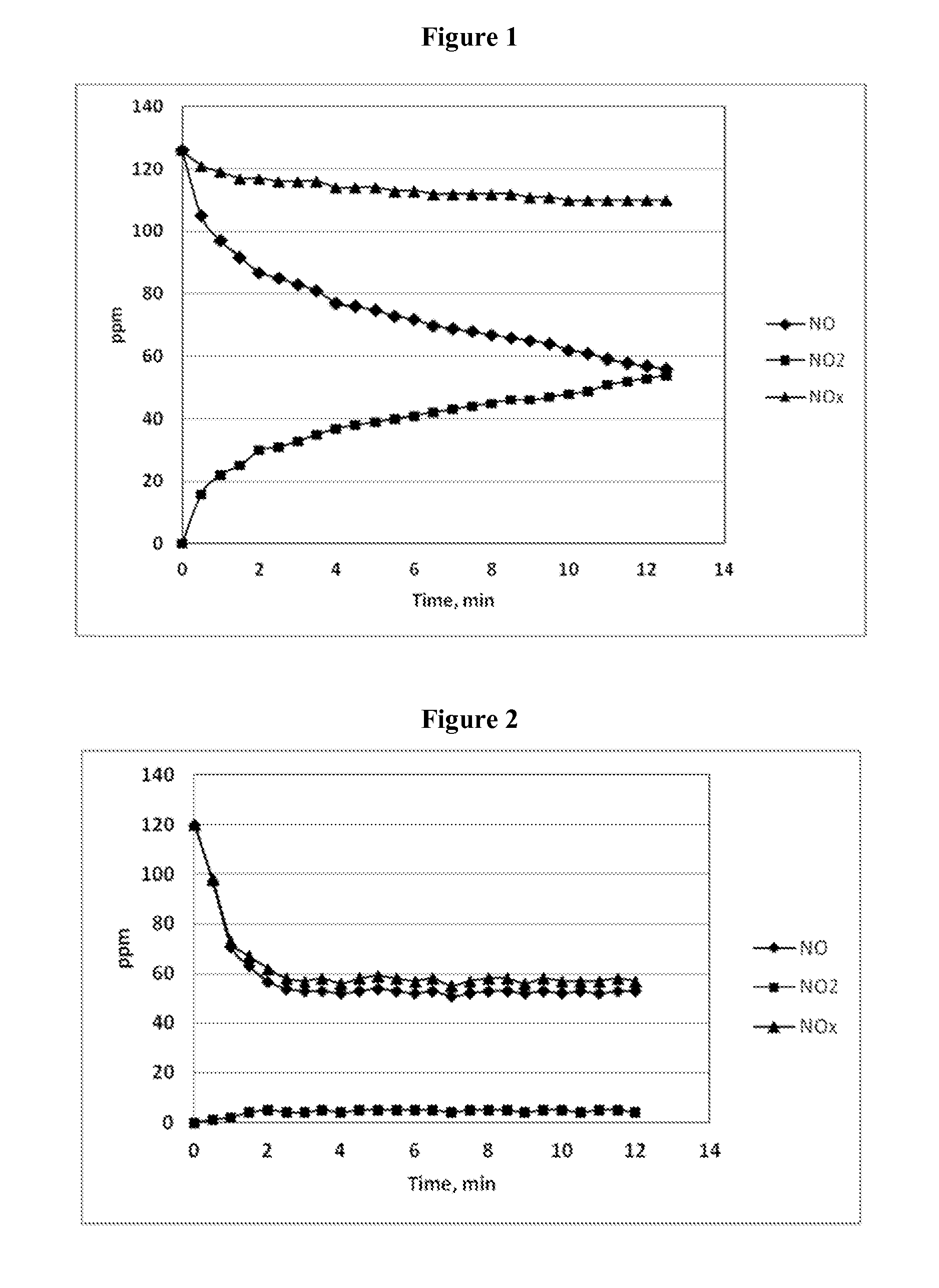
[0115]Example 2 studied the effect of using three different urea-to-hydrogen peroxide molar ratios on the removal of NO from a gas stream. The apparatus used for Example 2 was the same as that utilized in Example 1.

[0116]In Example 2, the urea (in solid form) or hydrogen peroxide (50% H2O2 source solution) was combined with carbamide peroxide and water to prepare aqueous solutions containing urea and hydrogen peroxide in three different molar ratios: 1.5:1, 1:1 and 0.67:1 urea:H2O2 in the aqueous reagent solutions.

[0117]All of these aqueous solutions, however, contained 5.0 wt. % urea—hydrogen peroxide reagent, the same solution concentrations of urea and hydrogen peroxide (corresponding to 3.2 wt. % urea and 1.8 wt. % H2O2) as were used in Example 1.

[0118]The molar ratio of H2O2:NO was kept constant in Example 2 at 2:1 H2O2:NO, so only the urea was varied with respect to the inlet NO concentration in these studies.

[0119]The temperature of the gas stream in the tube reactor was 405°...

example 3

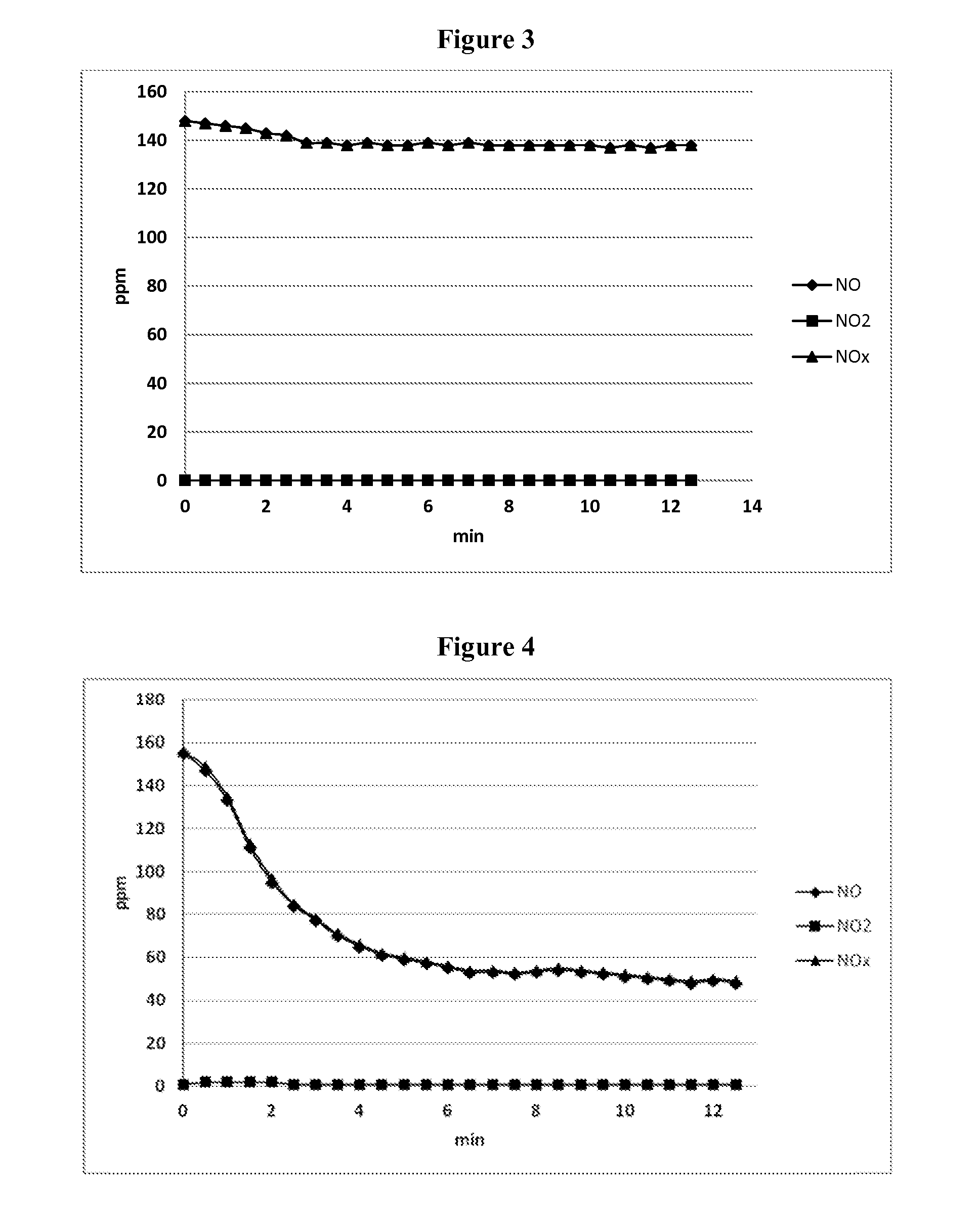
[0123]Example 3 studied the effect of gas stream temperature on the removal of NO from a gas stream, under otherwise fixed operating conditions, using the same urea-to-hydrogen peroxide molar ratio and hydrogen peroxide to NO molar ratio in each of the six temperature studies.

[0124]The apparatus used for Example 3 was the same as that utilized in Examples 1 and 2.

[0125]In Example 3, as in Example 1, the aqueous solution of the reagent was prepared by dissolution of carbamide peroxide, a solid adduct of urea and hydrogen peroxide, in water to prepare an aqueous solution that contained 5.0 wt. % carbamide peroxide, corresponding to 3.2 wt. % urea and 1.8 wt. % H2O2.

[0126]The molar ratio of urea to hydrogen peroxide in the aqueous reagent solution was therefore 1:1 urea:H2O2, as was the case in Example 1. The aqueous reagent solution was introduced into the gas stream in an amount that provided 2 moles of hydrogen peroxide to each mole of NO in the inlet gas stream. The ratio of urea t...


PUM

PropertyMeasurementUnit
temperatureaaaaaaaaaa

Abstract

A method for removing nitrogen oxides in stationary source combustion flue gas streams includes introducing a reagent or a mixture comprising carbamide peroxide and water as a reducing agent.

Description

PRIORITY CLAIM AND CROSS-REFERENCE[0001]This application claims the benefit of U.S. application Ser. No. 14 / 026,338, filed Sep. 13, 2013, which application is expressly incorporated by reference herein in its entirety.FIELD OF THE INVENTION[0002]The present invention relates to the treatment of a combustion flue gas stream from a stationary source to remove nitrogen oxide (NO) before the gas stream is released into the atmosphere.BACKGROUND OF THE INVENTION[0003]Combustion of fuels such as coal, coke, natural gas or oil typically results in the presence of pollutants in the combustion flue gas stream resulting from the combustion process or derived from impurities present in the fuel source. Electric utility power plants that burn coal are a significant source of such combustion process air pollutants, but other stationary fuel-burning facilities such as industrial boilers, waste incinerators, and manufacturing plants are also pollution sources.[0004]The primary air pollutants forme...

Claims


Application Information

Patent Timeline
Patent Type & Authority Patents(United States)
IPC IPC(8): B01D53/56
CPCB01D53/56B01D53/565B01D53/79B01D53/81B01D2251/106B01D2251/206B01D2257/404Y02A50/20
Inventor BLOCK, PHILIP A.HOLTZ, TIMOTHYPISANOVA, ELENAROVISON, JR., JOHN M.
Owner EVONIK OPERATIONS GMBH
Why Eureka
Try Eureka