Devices, systems and methods for creation of a peripherally located fistula

a peripherally located and device-based technology, applied in the field of medical devices and methods, can solve the problems of long recovery time and not always providing clear patient benefits, and achieve the effects of reducing neointimal proliferation, preventing tissue from protruding into the fistula flow path, and reducing bleeding of tissue neighboring

Inactive Publication Date: 2015-11-10
EDWARDS LIFESCIENCES CORP
View PDF45 Cites 13 Cited by
  • Summary
  • Abstract
  • Description
  • Claims
  • Application Information

AI Technical Summary

Benefits of technology

[0008]In a preferred embodiment, the device is configured to create a fistula to treat a patient suffering from COPD, such as via the fistula decreasing systemic vascular resistance of the patient. In these and other patient populations, the fistula may provide therapy by increasing the oxygen content of venous blood, such as blood supplied to a lung of the patient. The fistula may additionally cause oxygen content in arterial blood to also increase. The fistulas of the present invention are configured to have blood flow through the fistula of at least 5 ml / min, and preferably greater than 50 ml / min.
[0015]According to a fourth aspect of the invention, a method of creating a fistula is disclosed. The distal end of a fistula creation device is placed through the skin of the patient. The distal end, which is preferably the distal end of a sharpened, beveled tip needle assembly, such as a removable needle assembly, is advanced through a first vessel, such as a vein or an artery. The distal end is then advanced into a second vessel at an existing-fistula or an intended-fistula location. A fistula is then created, or an existing fistula is maintained, such that a long-term flow of blood is provided between the first vessel and the second vessel. The fistula creation device includes an elongate tubular structure that may be rigid along a majority of its length, may be flexible along a majority of its length, or may include rigid and flexible portions such as two rigid portions attached with a flexible hinge. In a preferred embodiment, blood flows from the first vessel to the second vessel. In an alternative, also preferred embodiment, blood flows from the second vessel to the first vessel. At the intended fistula location of the patient, the vessels may lie in various geometric configurations, such as wherein the first vessel is “on top” of the second vessel such that the lumen of the first vessel lies relatively proximate the shortest line between the lumen of the second vessel at the fistula location and the surface of the patient's skin. In alternative fistula locations, the vessels may lie in a more “side-to-side” configuration. When inserted, the elongate body of the fistula creation device is positioned to lie relatively in the plane defined by the lumens of the two vessels near the intended fistula location. While maintaining position within this plane, the fistula creation device can be inserted at an angle relatively perpendicular to the surface of the patient's skin, or at a smaller angle, such as an angle between 20 and 80 degrees. This insertion angle may be chosen by the clinician to affect the fistula angular geometry between the two vessels, such as at a small insertion angle to correspond to a similarly small angle between the lumen of the first vessel and the lumen of the fistula. Such a small angle between the first vessel lumen and the fistula lumen may be desirous to reduce turbulent flow through the fistula. In alternative embodiments, an insertion angle approximating ninety degrees may be chosen in order to minimize the length of the fistula.
[0018]In yet another preferred embodiment, an anastomotic implant is placed in the fistula. The anastomotic implant is placed to provide a function selected from the group consisting of: scaffolding an opening between the first vessel and the second vessel; reducing neointimal proliferation into the fistula flow path; preventing tissue from protruding into the fistula flow path; placing a portion of the first vessel wall in tension with the tissue of the second vessel wall; reducing bleeding of the tissue neighboring the fistula; enhancing healing of the tissue neighboring the fistula; and combinations thereof. The anastomotic implant may include one or more coatings, such as anti-bacterial; anti-thrombogenic and anti-prolific coatings. The anastomotic implant may additionally or alternatively include a covered portion, such as a partial covering, such covering materials selected from the group consisting of: polytetrafluoroethylene; Dacron; Nitinol; stainless steel; and combinations thereof. The fistula creation device of the present invention preferably places the anastomotic implant.

Problems solved by technology

It can be used on only a small percentage of the total patient population, requires long recovery times, and does not always provide a clear patient benefit.

Method used


Image

  • Devices, systems and methods for creation of a peripherally located fistula
  • Devices, systems and methods for creation of a peripherally located fistula
  • Devices, systems and methods for creation of a peripherally located fistula

Examples


Embodiment Construction

[0037]Reference will now be made in detail to the present embodiments of the invention, examples of which are illustrated in the accompanying drawings. Wherever possible, the same reference numbers will be used throughout the drawings to refer to the same or like parts.

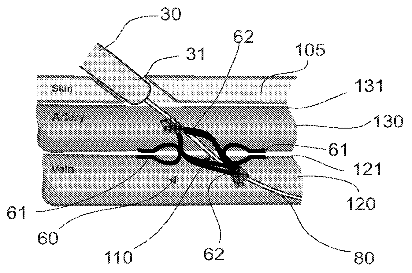
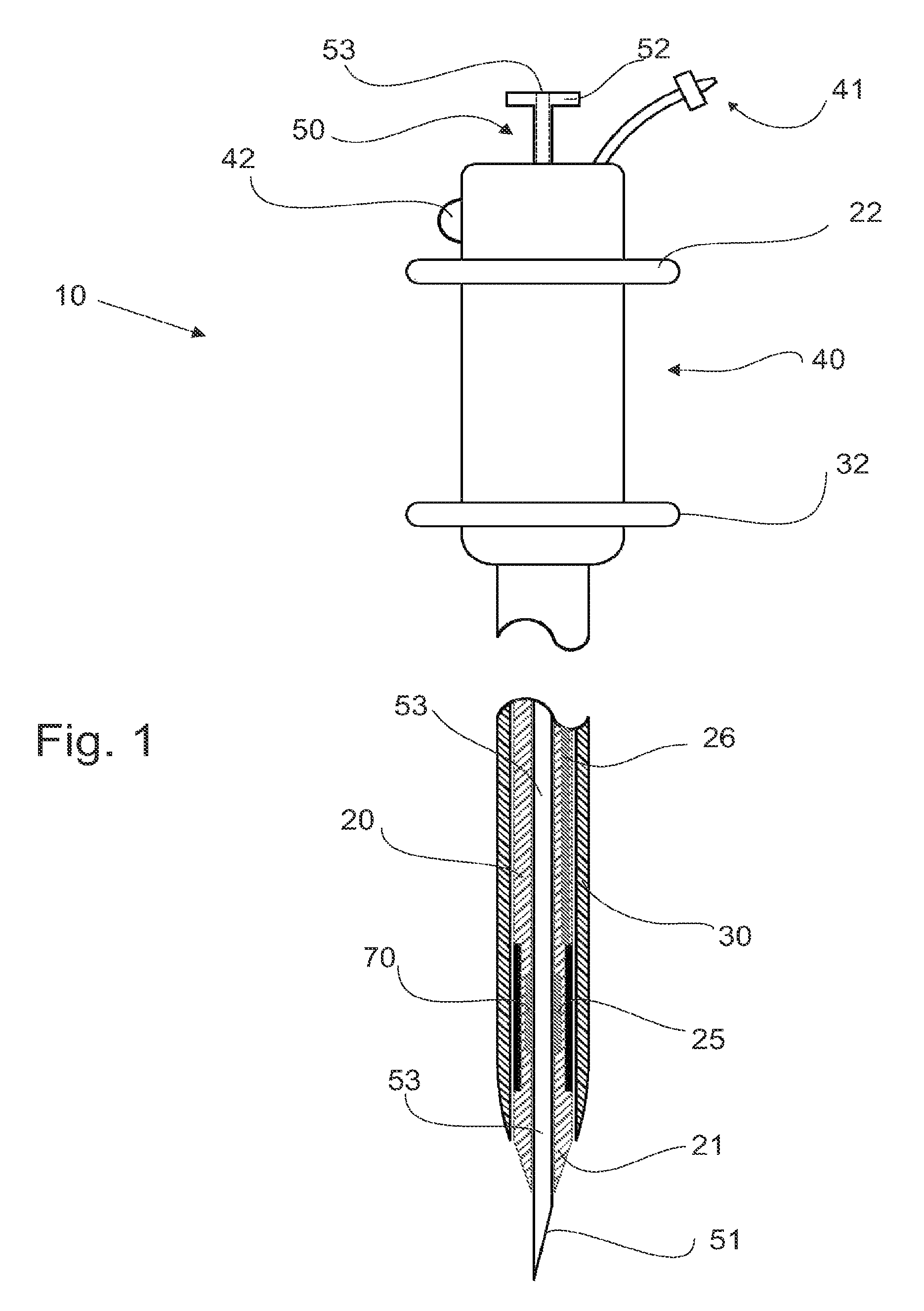
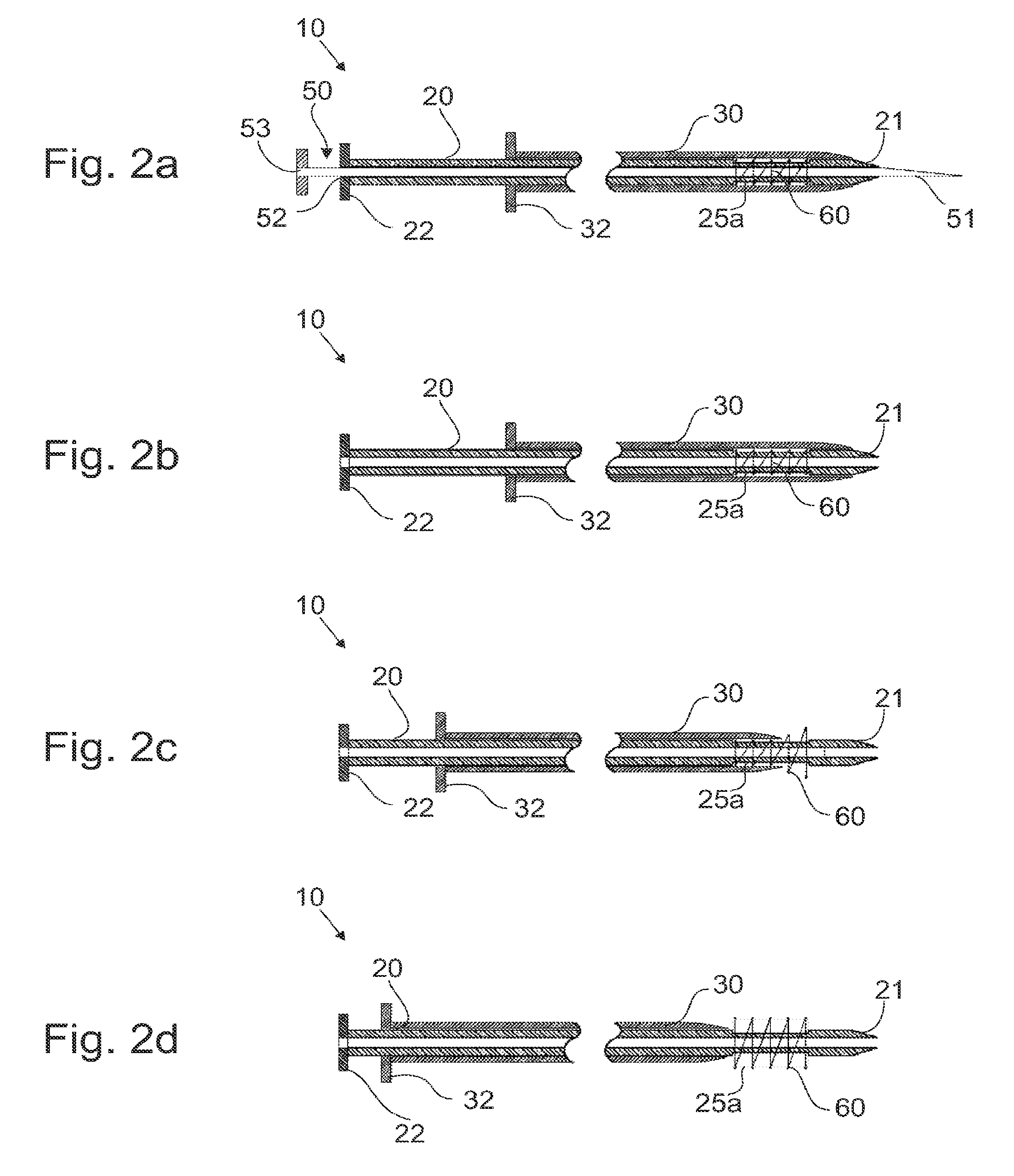
[0038]FIG. 1 depicts a preferred embodiment of the fistula creation device of the present invention. Device 10 is configured to be inserted by an operator through the skin of a patient to create and / or maintain a fistula that provides a flow of blood between a first vessel and a second vessel, such as a long-term flow of blood to achieve a therapeutic benefit. Device 10 includes an elongate tubular structure with a proximal end and a distal end, the tubular structure comprising multiple tubes that surround or are slidingly received within a separate tube. Each tube may have a rigid, semi-rigid, and / or flexible construction and each tube comprises one or more materials such as: nylon; polyvinyl chloride; polyethylene; ...


PUM


Abstract

Devices, systems and methods are disclosed for the formation of an arteriovenous fistula in the limb of the patient. Embodiments include a device for the creation, modification and maintenance of a fistula that includes an integral fistula creation assembly near its distal end that passes through the skin of the patient, through a first vessel such as an artery, and into a second vessel such as a vein. The fistula creation assembly preferably includes an anastomotic implant that is placed within the fistula to maintain long-term blood flow therethrough. The devices, systems and methods can be used to treat patients with one or more numerous ailments including chronic obstructive pulmonary disease, congestive heart failure, hypertension, hypotension, respiratory failure, pulmonary arterial hypertension, lung fibrosis and adult respiratory distress syndrome.

Description

CROSS-REFERENCE TO RELATED APPLICATIONS[0001]This application is a continuation of U.S. patent application Ser. No. 11 / 946,454 (now U.S. Pat. No. 8,641,724), filed Nov. 28, 2007, which is a continuation of PCT / US2006 / 024858, filed on Jun. 26, 2006, which claims priority from U.S. Application No. 60 / 696,319, filed on Jun. 30, 2005, the full disclosures of each which are incorporated herein by reference.BACKGROUNDField of the Invention[0002]The present invention relates generally to medical devices and methods. More particularly, the present invention relates to devices and methods for creating or modifying a fistula between a first vessel and a second vessel, such as for the treatment of chronic obstructive pulmonary disease.[0003]Chronic obstructive pulmonary disease affects millions of patients in the United States alone. The present standard of care is externally supplied oxygen therapy, which requires a patient to remain near a stationary oxygen source or carry a bulky oxygen sou...

Claims


Application Information

Patent Timeline
Patent Type & Authority Patents(United States)
IPC IPC(8): A61B17/08A61B17/34A61B17/11A61B17/122
CPCA61B17/11A61B17/3468A61B17/122A61B2017/1107A61B2017/1139A61B8/488A61B17/083A61B17/3403A61B2017/3413A61M25/09
Inventor BRENNEMAN, RODNEYSCHAEFER, DEAN A.FLAHERTY, J. CHRISTOPHER
Owner EDWARDS LIFESCIENCES CORP
Why Eureka
Try Eureka