Filter media for a liquid filter using an electrospun nanofiber web, method for manufacturing same, and liquid filter using same

a technology of nanofiber webs and filter media, which is applied in the direction of membranes, filtration separation, separation processes, etc., can solve the problems of low filter efficiency, high energy costs, and liquid cannot easily pass through the conventional filter, so as to maximize filter efficiency, prevent degradation of filter efficiency, and good durability

Active Publication Date: 2015-12-29
AMOGREENTECH CO LTD
View PDF11 Cites 12 Cited by
  • Summary
  • Abstract
  • Description
  • Claims
  • Application Information

AI Technical Summary

Benefits of technology

[0018]To solve the above problems or defects, it is an object of the present invention to provide a filter medium for a liquid filter, using a nanofiber web having air-electrospun (AES) three-dimensional micropores as membranes, to thus exert good durability and utilize a hydrophobic resin as well as a hydrophilic resin due to capillarity, and a method of manufacturing the filter medium.
[0019]It is another object of the present invention to provide a filter medium for a liquid filter, in which membranes of a multi-layered structure are stacked, to thus perform depth filtration as well as surface filtration and to thereby maximize filter efficiency, a method of manufacturing the filter medium, and a liquid filter using the filter medium.
[0020]It is still another object of the present invention to provide a filter medium for a liquid filter, having fine pores in size by performing a high-temperature and high-pressure calendering process, so as to be thin and light but to prevent degradation of filter efficiency due to a multi-layered structure, and a method of manufacturing the filter medium.

Problems solved by technology

Here, since a pore structure is a closed pore structure of the two-dimensional geometry, filter efficiency is low.
In addition, since a pore structure is a closed pore structure of the two-dimensional geometry in the case of using a hydrophobic polymer such as PTFE (polytetrafluoroethylene) in a conventional filter, liquid does not pass through the conventional filter easily.
As a result, problems such as high energy costs, frequent filter replacement, and a low flow rate of water are pointed out.
Thus, there is a problem that it is difficult of bending a porous membrane medium and putting a lot of threads per inch in a filter.
Accordingly, unless the fibers have micropores, they are not uniformly distributed and pores are uneven.
Also, since contaminants exit concentratively through large pores, filter efficiency is low.
However, excessive calendering clogs pores and thus porosity becomes small.
Accordingly, if calendered nonwovens are used in liquid filters, a filter pressure becomes high and pores are quickly clogged, to thus cause a negative effect upon a filter life.
Thus, even if a liquid processing module is manufactured by using the existing membrane technology, a fluid flow is lowered due to a membrane clogging phenomenon and a driving pressure rises.
The membrane clogging phenomenon is severe especially in the high concentration fluid, and it was impossible to apply the membrane technology for the high concentration and high turbidity fluid.
However, the method of forming a fiber web of nanofibers in the Korean Laid-Open Patent Publication No. 2008-60263 cannot be called a manufacturing technology of using a multi-hole spin pack.
As a result, since solidification takes place at the surface of the solution, it is difficult to perform spinning for a long time.
Also, since fibers increase in diameter, a fiber web of micrometers or less cannot be formed.
Furthermore, in the case that the ultrafine fiber web obtained by electrospinning does not go through a pretreatment process of appropriately adjusting the amount of the solvent and moisture remaining on the surface of the web before performing calendering, pores are increased but the strength of the web is weakened.
Otherwise, in the case that evaporation of the solvent is not performed too slowly, a phenomenon of melting the web may occur.

Method used


Image

  • Filter media for a liquid filter using an electrospun nanofiber web, method for manufacturing same, and liquid filter using same
  • Filter media for a liquid filter using an electrospun nanofiber web, method for manufacturing same, and liquid filter using same
  • Filter media for a liquid filter using an electrospun nanofiber web, method for manufacturing same, and liquid filter using same

Examples


example 1

PAN 12 wt %−DMAc

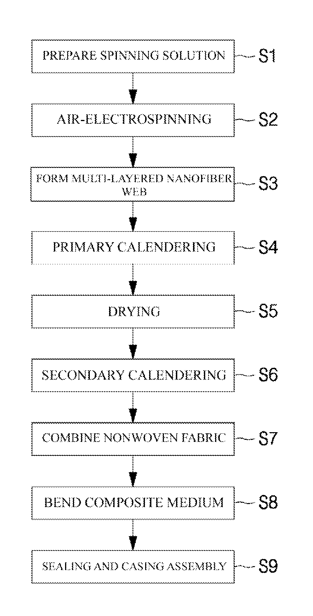
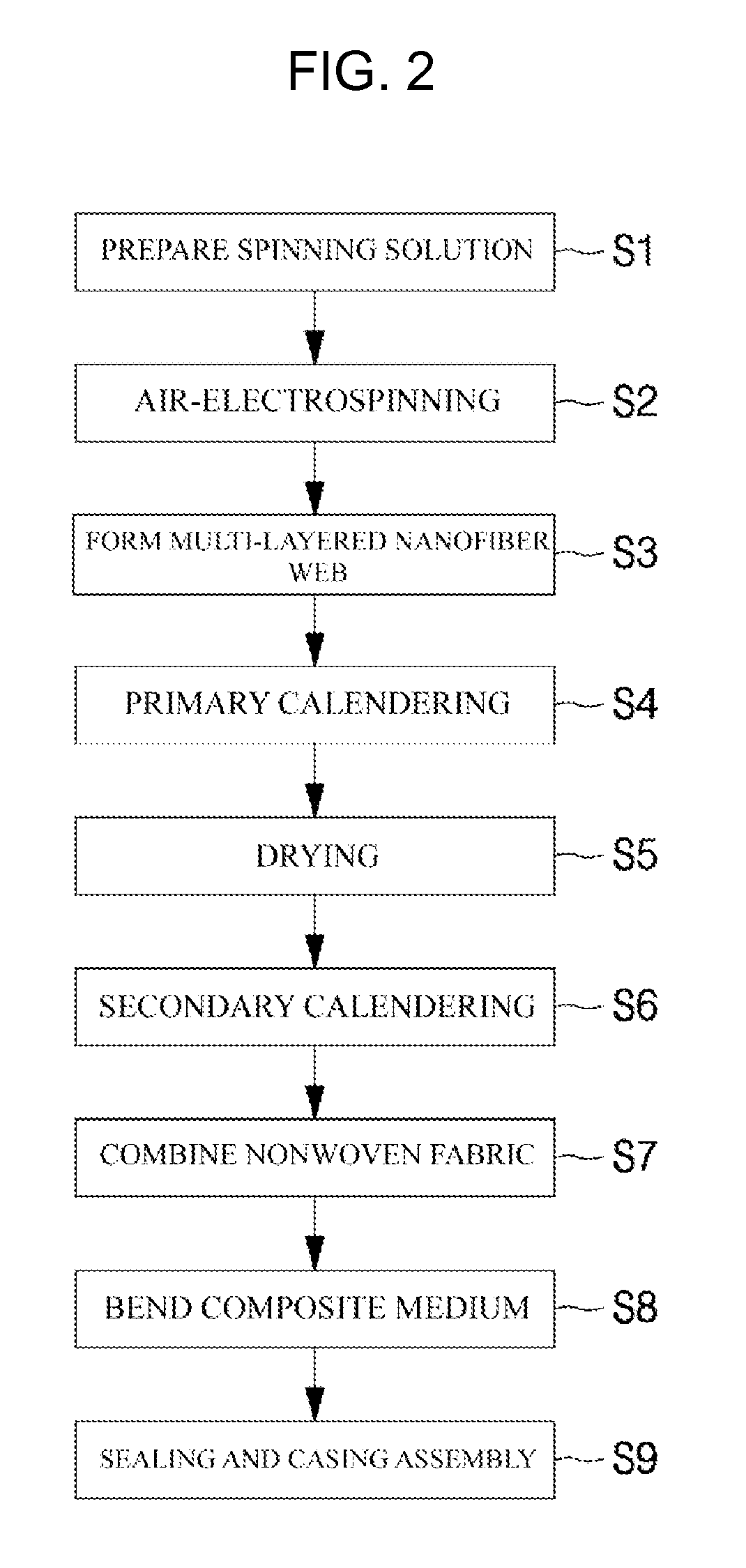
[0126]In order to manufacture a liquid filter containing a nanofiber medium by air-electrospinning (AES), polyacrylonitrile of about 12 g was added to a solution of dimethylacetamide (DMAc) of about 88 g, and stirred at about 80° C., to thus have prepared a spinning solution.

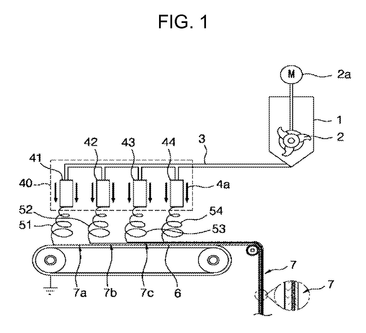
[0127]The prepared spinning solution was injected into a tank, and was discharged as the polymer solution at about 20 ul / min / hole. Here, while maintaining the spinning temperature at about 28° C., and the spinning humidity at about 60%, a voltage of about 110 KV was applied to a spin nozzle pack by using a high-voltage generator, and simultaneously an air pressure of about 0.4 MPa per spin pack nozzle was applied thereto, to thus have prepared a PAN ultrafine fiber web.

[0128]In order to increase the strength of the thus-prepared ultrafine fiber web, the ultrafine fiber web was made to undergo a primary drying process at a running time (RT) of about 5 min / m, in which air of about 30° C. was circul...

example 2

[0130]PVdF 12 wt %−Acetone: DMAc=3:7

[0131]In order to manufacture a liquid filter containing a nanofiber medium by air-electrospinning (AES), PVdF (polyvinylidenefluoride) of about 12 g was added to a solution of a mixture of dimethylacetamide (DMAc) of about 61.6 g and acetone of about 26.4 g, and stirred at about 80° C., to thus have prepared a spinning solution.

[0132]The prepared spinning solution was injected into the tank, and was discharged as the polymer solution at about 17.5 ul / min / hole. Here, while maintaining the spinning temperature at about 28° C., and the spinning humidity at about 60%, a voltage of about 105 KV was applied to the spin nozzle pack by using the high-voltage generator, and simultaneously an air pressure of about 0.25 MPa per spin pack nozzle was applied thereto, to thus have prepared a PVdF ultrafine fiber web.

[0133]In order to increase the strength of the thus-prepared ultrafine fiber web, the ultrafine fiber web was made to undergo the primary drying p...

example 3

PVdF 16.5 wt %−Acetone: DMAc=2:8

[0135]In order to manufacture a liquid filter containing a nanofiber medium by air-electrospinning (AES), PVdF (polyvinylidenefluoride) of about 15 g was added to a solution of a mixture of dimethylacetamide (DMAc) of about 66.8 g and acetone of about 16.7 g, and stirred at about 80° C., to thus have prepared a spinning solution.

[0136]The prepared spinning solution was injected into the tank, and was discharged as the polymer solution at about 17.5 ul / min / hole. Here, while maintaining the spinning temperature at about 28° C., and the spinning humidity at about 60%, a voltage of about 108

[0137]KV was applied to the spin nozzle pack by using the high-voltage generator, and simultaneously an air pressure of about 0.25 MPa per spin pack nozzle was applied thereto, to thus have prepared a PVdF ultrafine fiber web.

[0138]In order to increase the strength of the thus-prepared ultrafine fiber web, the ultrafine fiber web was made to undergo the primary drying ...


PUM

PropertyMeasurementUnit
speedaaaaaaaaaa
pore sizeaaaaaaaaaa
thickaaaaaaaaaa

Abstract

Provided is a filter medium for a liquid filter, having a three-dimensional micropore structure of a multi-layered structure using a multilayer nanofiber web that is obtained by performing air-electrospinning, to thus be thin but have high efficiency and long life, a method of manufacturing the filter medium using the multilayer nanofiber web, and a liquid filter using the filter medium. The filter medium for a liquid filter, includes: a nanofiber web that is made by stacking nanofibers that are obtained by air-electrospinning a fibrous polymer material and that have micropores; and a supporter that is inserted and combined onto one surface or in an inner portion of the nanofiber web.

Description

TECHNICAL FIELD[0001]The present invention relates to a filter medium for a liquid filter, using a multi-layered structure of a nanofiber web having air-electro spun (AES) three-dimensional micropores as membranes, to thus exert good durability and utilize a hydrophobic resin as well as a hydrophilic resin due to capillarity, a method of manufacturing the filter medium, and a liquid filter using the filter medium.BACKGROUND ART[0002]As a technology of manufacturing membranes and a membrane application technology have been recently dramatically developed, a membrane technology is widely used in liquid processing fields such as removal of contaminants from liquid, or separation, enrichment and recovery of useful materials from liquid.[0003]Existing membrane technologies are being replaced by membrane technologies because of constant performance and stability according to membrane pore sizes, and due to convenience and concise system according to automation.[0004]There are porous membr...

Claims


Application Information

Patent Timeline
Patent Type & Authority Patents(United States)
IPC IPC(8): B01D69/06B01D71/46B01D29/00B01D39/16B01D67/00B82Y40/00B01D39/00
CPCB01D67/0013B01D39/1623B01D29/0093B01D71/46B01D2239/025B01D2239/065B01D2239/0631B01D2239/0654B01D2239/10B01D2323/39B01D2323/42B82Y40/00Y10S977/778Y10S977/89Y10S977/902B01D39/14B01D69/00D01D5/00D04H3/16
Inventor SEO, IN YONGLEE, SEUNG HOONJUNG, YONG SIK
Owner AMOGREENTECH CO LTD
Why Eureka
Try Eureka