
Method for producing concave-convex substrate using sol-gel method, sol used in same, method for producing organic EL element using same, and organic EL element obtained thereby

a technology of concave and convex substrates, which is applied in the direction of electric lighting sources, solid-state devices, and short-wavelength light sources, can solve the problems of difficult development of light sources, difficulty in technical and economic aspects, and high cost of short-wavelength light sources, and achieves large area, high yield, and reliable transfer of concave and convex patterns.

Inactive Publication Date: 2015-12-29
JX NIPPON OIL & ENERGY CORP
View PDF14 Cites 2 Cited by
  • Summary
  • Abstract
  • Description
  • Claims
  • Application Information

AI Technical Summary

Benefits of technology

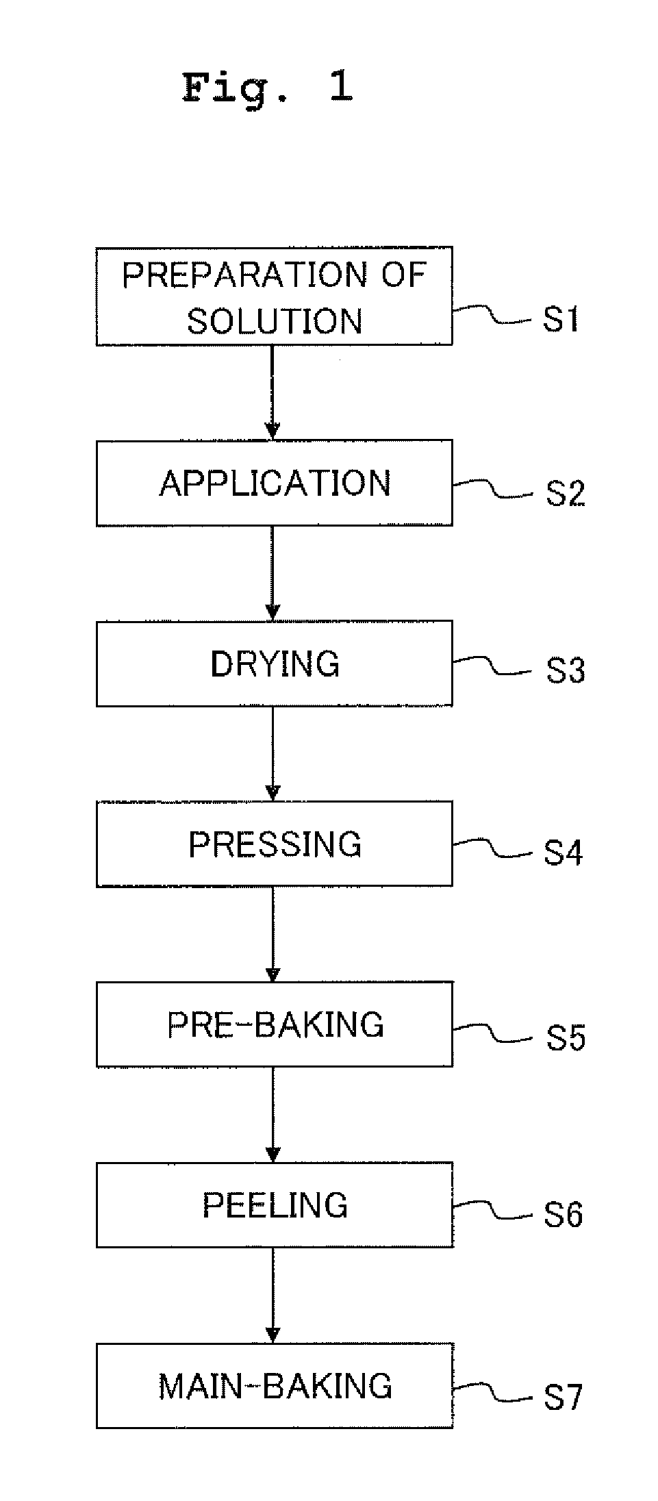
[0023]In the peeling step, a peeling roll is preferably used to peel off the mold from the coating film easily. Especially, the peeling roll is heated to peel off the mold from the coating film more easily.
[0024]The average pitch of concavities and convexities on the concavity and convexity pattern may be in a range of 100 nm to 900 nm and especially in a range of 100 nm to 600 nm. The average height of the concavities and convexities may be in a range of 20 nm to 200 nm. The mold having the concavity and convexity pattern may be a flexible mold. In a case that the flexible mold is used, the flexible mold may be a long mold having a length longer than that of the substrate from a viewpoint of improving the productivity. The long mold can be pressed against the coating film with the pressing roll while being transported by use of a feeding roll which feeds the long mold and a winding roll which winds or rolls up the long mold thereon.
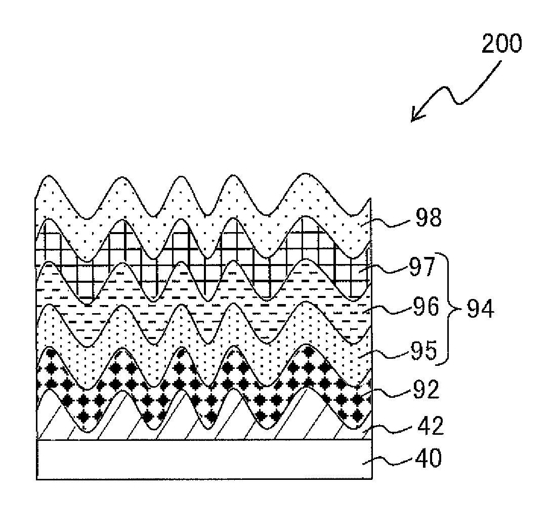
[0025]According to the second aspect of the present invention, there is provided a method for producing an organic EL element, wherein a diffraction-grating substrate having a concavity and convexity surface is manufactured by the method for producing the substrate having the concavity and convexity pattern as defined in the first aspect; and a transparent electrode, an organic layer, and a metal electrode are stacked in this order on the concavity and convexity surface of the diffraction-grating substrate, thereby producing the organic EL element.
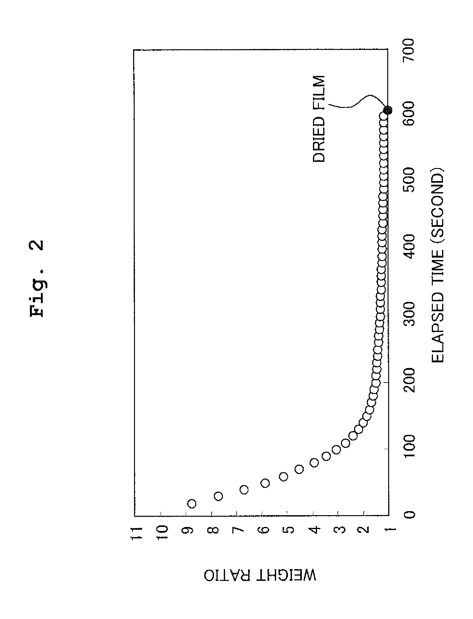
[0028]According to the present invention, by drying the coating film so that the ratio of weight of the coating film to the dried weight of the coating film is in a range of 1.4 to 8.8, the dried weight being obtained by baking the coating film having a relatively large area at a temperature of 100 degrees Celsius, it is possible to reliably transfer the concavity and convexity pattern from the mold to the coating film by use of the pressing roll in a short time after the drying step. Therefore, it is possible to produce a substrate, which has a relatively large area, with a coating film, which has a minute concavity and convexity pattern, at a high yield. Further, the yield can be further improved by performing the pressing step while heating the coating film. Since the concavity and convexity pattern of the substrate is made of silica by the sol-gel process, the substrate obtained by the method of the present invention is a substrate which may be resistant to a high temperature process performed when the organic EL element is produced. The organic EL element produced by the present invention has excellent durability and satisfactory light resistance.

Problems solved by technology

However, the light source having the short wavelength is expensive, development thereof is not easy, and the development of an optical material transmitting such a short-wavelength light is also needed.
Further, manufacturing a large-area pattern by a conventional lithography method needs a large-size optical element, and thus there are difficulties in technical and economic aspects.
However, the photo-curable resin described above generally has a low heat resistance, and decomposed and / or turns into yellow at a high temperature.
Thus, there is fear that a film having the minute pattern is decomposed in a case that a high temperature treatment is included in subsequent steps.
Further, the photo-curable resin has a low adhesion property to a glass substrate.
Furthermore, in a case that the resin layer to which the pattern has been transferred is used for an element such as the organic EL element, there is fear that impurities are eluted from the resin layer and cause adverse effect on the element.
However, the thermal nanoimprint method generally needs a high pressure for pressing, and takes time for a heating-cooling cycle.
Thus, the thermal nanoimprint method is unsuitable for a case in which high productivity is desired.
Further, the thermal nanoimprint method has the problem of the heat resistance since the thermoplastic resin is heated and softened to perform the transfer.
For example, in a case that the transfer-target object is exposed to a temperature higher than a molding temperature, there is a fear that the pattern is deformed and thereby it can not be used.
Especially, a nanoimprint molded product using an inorganic sol-gel material has a high heat resistance, and any problem is unlikely to occur even when a high temperature treatment is performed.
However, the pressing method using the sol-gel material also has the following problem.
Further, since a solvent positioned in the center of the mold having the flat plate shape used for the pressing is less likely to evaporate, transfer failure occurs in the center of the mold and / or unevenness of the transfer occurs owing to the difference in a cured state of the surface.
The above problems become especially conspicuous when the transfer pattern is formed in a large area.
The solvent evaporates from an end portion of the coating film, and a heating process is required for a long time at a low temperature (for example, 120 degrees Celsius) in order to evaporate the solvent completely, which decreases the productivity.
Further, since the surface of the mold having the flat plate shape needs to be pressed uniformly at the same time, a relatively great transfer pressure is required.
Thus, when the transfer pattern has the large area, it is difficult to press the surface of the mold uniformly under the great pressure.
Moreover, when the mold is peeled off from the base member, a great peeling force is required to pull up the mold in a vertical direction.
Therefore, there is fear that a sol-gel material layer is broken at the time of the peeling of the mold from the sol-gel material layer, and thereby the pattern is collapsed.
As described above, there are many problems to perform the press transfer to a large area by use of the mold having the flat plate shape.
However, the roll press method using the sol-gel material also has the following problem.
However, since the time-dependent change of evaporation of the solvent in a gelled state is rapid, if the control is not performed precisely after the sol is applied on the substrate and before the concavity and convexity pattern is pressed by the roll press, the failure arises such that depths of concavities and convexities are insufficient and that the transfer pattern can not be obtained.

Method used


Image

  • Method for producing concave-convex substrate using sol-gel method, sol used in same, method for producing organic EL element using same, and organic EL element obtained thereby
  • Method for producing concave-convex substrate using sol-gel method, sol used in same, method for producing organic EL element using same, and organic EL element obtained thereby
  • Method for producing concave-convex substrate using sol-gel method, sol used in same, method for producing organic EL element using same, and organic EL element obtained thereby

Examples


example 1

[0089]2.5 g of tetraethoxysilane (TEOS) and 2.1 g of methyltriethoxysilane (MTES) were added by drops to a mixture of 24.3 g of ethanol, 2.16 g of water, and 0.0094 g of concentrated hydrochloric acid, followed by being stirred for 2 hours at a temperature of 23 degrees Celsius and humidity of 45% to obtain a sol. The sol was applied on a soda-lime glass plate of 15×15×0.11 cm by a bar coating. Doctor Blade (manufactured by Yoshimitsu Seiki Co., Ltd.) was used as a bar coater. The doctor blade was designed so that the film thickness of the coating film was 5 μm. However, the doctor blade was adjusted so that the film thickness of the coating film was 40 μm by sticking an imide tape having a thickness of 35 μm to the doctor blade. The weight of the glass plate (glass substrate) after the bar coating was weighed every time when a predetermined period of time elapses by use of an electric weighing machine (produced by Kensei Industry Co., Ltd., electromagnetic weighing machine “GH-202”...

example 2

[0097]A sol was prepared in the same manner as Example 1, except that 31.7 g of isopropyl alcohol (IPA) was used instead of ethanol used in the sol. A spin coating method was used as the method for applying the sol other than the bar coating method. The spin coating was performed at a spin speed of 500 rpm for 8 seconds, and then performed at a spin speed of 1000 rpm for 3 seconds. The weight of the glass substrate was weighed for each elapsed time after the spin coating in the same manner as Example 1. Then, it was obtained the ratio of weight of the glass substrate to the weight (dried weight) of the substrate, the dried weight being obtained by heating the substrate at a temperature of 100 degrees Celsius for 5 minutes. FIG. 15 shows the variation of the ratio (e=b(t) / a) of weight of the coating film to the dried weight of the coating film for each elapsed time after the spin coating. Subsequently, the mold was pressed against the coating film of the sol, which was obtained by pe...

example 3

[0100]In this Example, a mold having a concave and convex surface was produced by using the BCP method, and then a diffraction grating and an organic EL element including the diffraction grating were produced using the produced mold and the pressing roll used in Example 1. At first, it was prepared a block copolymer produced by Polymer Source Inc., which was made of polystyrene (hereinafter referred to as “PS” in an abbreviated manner as appropriate) and polymethyl methacrylate (hereinafter referred to as “PMMA” in an abbreviated manner as appropriate) as described below.[0101]Mn of PS segment=868,000[0102]Mn of PMMA segment=857,000[0103]Mn of block copolymer=1,725,000[0104]Volume ratio between PS segment and PMMA segment (PS:PMMA)=53:47[0105]Molecular weight distribution (Mw / Mn)=1.30[0106]Tg of PS segment=96 degrees Celsius[0107]Tg of PMMA segment=110 degrees Celsius

[0108]The volume ratio of the first polymer segment and second polymer segment (the first polymer segment:the second ...


PUM

PropertyMeasurementUnit
temperatureaaaaaaaaaa
temperaturesaaaaaaaaaa
heightaaaaaaaaaa

Abstract

A method for producing a substrate having a concavity and convexity pattern includes: a step for applying a sol containing a silica precursor on a substrate to form a coating film; a step for drying the coating film; a pressing step for pressing a mold having a concavity and convexity pattern against the dried coating film with a pressing roll; a step for peeling off the mold from the coating film; and a step for baking the coating film to which the concavity and convexity pattern has been transferred. The coating film is dried in the drying step so that the ratio of weight of the coating film to dried weight of the coating film is in a range of 1.4 to 8.8, the dried weight being obtained by baking the coating film at a temperature of 100 degrees Celsius. The coating film may be heated in the pressing step.

Description

CROSS REFERENCE TO RELATED APPLICATION[0001]This application is a continuation application of International Patent Application No. PCT / JP2012 / 070854 filed on Aug. 16, 2012 claiming the benefit of priority of Japanese Patent Applications No. 2011-239567 filed on Oct. 31, 2011, No. 2011-247074 filed on Nov. 11, 2011, No. 2012-154873 filed on Jul. 10, 2012 and No. 2012-154880 filed on Jul. 10, 2012. The contents of International Patent Application No. PCT / JP2012 / 070854 and Japanese Patent Applications No. 2011-239567, No. 2011-247074, No. 2012-154873 and No. 2012-154880 are incorporated herein by reference in their entities.BACKGROUND OF THE INVENTION[0002]1. Field of the Invention[0003]The present invention relates to a method for producing a substrate having a minute or fine pattern by use of a transfer roll, a method for producing an organic EL element (Organic Electro-Luminescence element or organic light emitting diode) using the same, and the organic EL element obtained thereby. ...

Claims


Application Information

Patent Timeline
Patent Type & Authority Patents(United States)
IPC IPC(8): H01L51/52B29C59/04B29C59/02H01L51/00H01L51/56B29C35/02B29C35/04B29C35/08
CPCB29C59/022B29C59/026B29C59/046H01L51/0014H01L51/5275H01L51/56H01L51/5262B29C2035/0822B29C35/02B29C2035/046H10K71/20H10K50/858H10K71/00B29C59/04H01L21/027H10K50/00H05B33/10H10K50/85
Inventor TAKAHASHI, MADOKAKUMAGAI, YOSHIHIRONISHIMURA, SUZUSHI
Owner JX NIPPON OIL & ENERGY CORP
Learn More