Method and apparatus for improved turbine bellyband rotor seal machining, installation and life

a technology for machining and rotor sealing, which is applied in the direction of turbines, machines/engines, manufacturing tools, etc., can solve the problems of traditional methods suffering from several drawbacks, parts will inevitably need to be replaced, and the bellyband often reaches the end of life, so as to improve the rotor seal machining and installation and life, and the effect of uniform size and shap

Active Publication Date: 2016-03-01
SIEMENS ENERGY INC
View PDF2 Cites 3 Cited by
  • Summary
  • Abstract
  • Description
  • Claims
  • Application Information

AI Technical Summary

Benefits of technology

[0007]In accordance with the teachings of the present invention, a method and apparatus for improved turbine bellyband rotor seal machining, installation and life are disclosed. A fixture is provided which can be temporarily attached to the turbine disks in a position straddling a gap between the disks, without destacking the turbine rotor. The fixture accepts power tools including a drill and a mill, and positions the power tools to drill and grind a rectangular slot into the disks, where the slot has the exact size and shape needed to receive an anti-rotation block which is integral to the replacement bellyband. Measuring tools are also provided which enable precise location of each of the four slots which must be machined in the disks. The resulting slots have a uniform size and shape, and are equally spaced around the circumference of the disk, thereby facilitating installation of the service bellyband from four identical segments.

Problems solved by technology

However, due to the long service life of modern gas turbines, some parts will inevitably need to be replaced.
Because of the extreme heat and corrosive nature of the gases to which it is exposed, the bellyband often reaches its end of life and needs to be replaced before the turbine itself is due to be retired.
These traditional methods suffer from several drawbacks.
One drawback is that, despite best efforts at manual measurement of the slot locations, the four segments that make up the replacement bellyband often end up having slightly different lengths—meaning that each segment becomes a turbine-specific service part.
Another drawback is that the manually machined slots in the rotor disks inevitably have a slightly irregular and non-optimal shape, which causes excess stress on both the rotor disks themselves and the replacement bellyband.
These drawbacks add complexity to the service replacement of bellybands, and reduce the life of the service bellybands, both of which are undesirable.

Method used


Image

  • Method and apparatus for improved turbine bellyband rotor seal machining, installation and life
  • Method and apparatus for improved turbine bellyband rotor seal machining, installation and life
  • Method and apparatus for improved turbine bellyband rotor seal machining, installation and life

Examples


Embodiment Construction

[0025]The following discussion of the embodiments of the invention directed to a method and apparatus for improved turbine bellyband rotor seal machining and installation is merely exemplary in nature, and is in no way intended to limit the invention or its applications or uses.

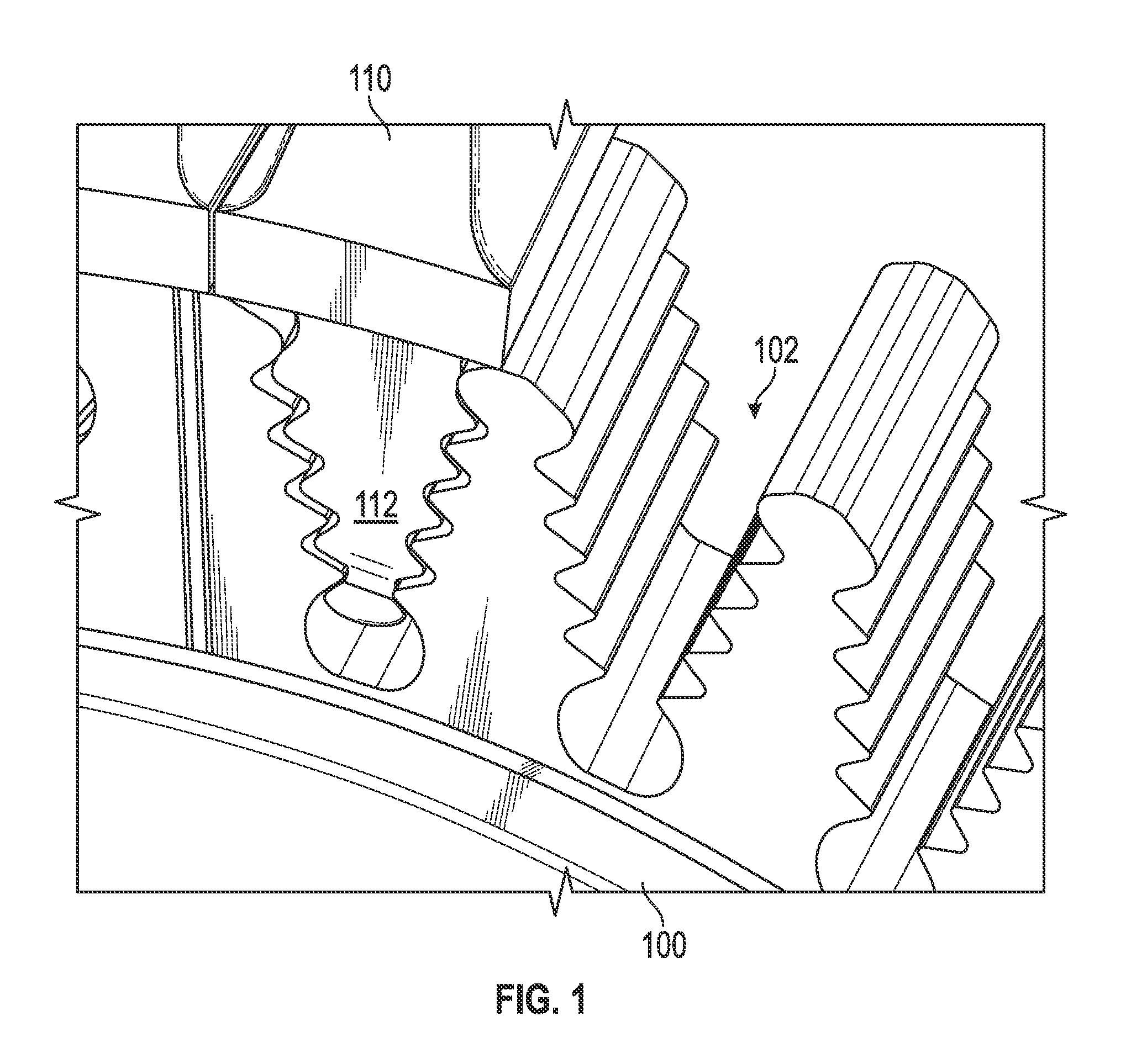
[0026]FIG. 1 is an illustration of a gas turbine rotor disk 100 and a plurality of turbine blades 110. In this design, the blade 110 has a blade root 112 with an inverted “fir tree” shape, and the rotor disk 100 has a complementary fir tree shaped cavity 102. The turbine blade 110 can be installed in the rotor disk 100 by simply sliding the blade 110 in a longitudinal direction (parallel to the rotational axis of the turbine) so that the fir tree shape of the blade root 112 engages with the mating cavity 102 in the rotor disk 100. In one typical gas turbine design, there are four of the disks 100—each with its respective set of the blades 110—arranged axially along a rotor shaft (not shown) in the turbine.

[00...


PUM

PropertyMeasurementUnit
circumferenceaaaaaaaaaa
distanceaaaaaaaaaa
sizeaaaaaaaaaa

Abstract

A method and apparatus for improved turbine bellyband rotor seal machining, installation and life are disclosed. A fixture is provided which can be temporarily attached to the turbine disks in a position straddling the gap between the disks, without destacking the turbine rotor. The fixture accepts power tools including a drill and a mill, and positions the power tools to drill and grind a rectangular slot into the disks, where the slot has the exact size and shape needed to receive an anti-rotation block which is integral to the replacement bellyband. Measuring tools are also provided which enable precise location of each of the four slots which must be machined in the disks. The resulting slots have a uniform size and shape, and are equally spaced around the circumference of the disk, thereby facilitating installation of the service bellyband from four identical segments.

Description

BACKGROUND OF THE INVENTION[0001]1. Field of the Invention[0002]This invention relates generally to improving the service installation of a bellyband seal between rotor disks in a gas turbine and, more particularly, to a method and corresponding fixtures and gages for installing a replacement bellyband in a turbine without destacking the rotor, including a compact machining fixture which can be used to precisely machine the rotor disks to accept engagement features of the bellyband, and layout tools for precisely locating the machining sites.[0003]2. Description of the Related Art[0004]Combustion gas turbines are clean-burning, efficient devices for generating power for a variety of applications. One common application of combustion gas turbines is in power plants, where the turbine drives a generator which produces electricity. Such stationary gas turbines have been developed over the years to improve reliability and efficiency. However, due to the long service life of modern gas t...

Claims


Application Information

Patent Timeline
Patent Type & Authority Patents(United States)
IPC IPC(8): F02C7/28B23P6/00B23B47/28B23B49/00B23P13/02
CPCF02C7/28B23B47/28B23B49/00B23P6/002B23P13/02F05D2230/80F01D11/005F01D25/285B23C3/30B23B2215/76B23C2220/366B23C9/00
Inventor BIRD, DEREK, A.MITCHELL, DAVID, J.OLEJARSKI, MICHAEL, J.
Owner SIEMENS ENERGY INC
Why Eureka
Try Eureka