Bone-anchoring or bone-connecting device that induces a strain stimulus

a bone-anchoring or bone-connecting technology, applied in the field of implants in the form of implants, can solve the problems of screw loosening, bone necrosis, and loss of structural integrity, and achieve the effects of reducing implant loosening, increasing anchoring strength with the bone, and reducing the loosening of implants

Active Publication Date: 2016-03-15
ACES
View PDF15 Cites 2 Cited by
  • Summary
  • Abstract
  • Description
  • Claims
  • Application Information

AI Technical Summary

Benefits of technology

[0015]An advantageous feature of the present invention is that the implant according to the invention exerts a strain stimulus on the surrounding bone tissue and induces the “modelling” process. This increases the anchoring strength with the bone and therefore reduces implant loosening. A major advantage is that the relatively high, physiologically effective strains on the surface can be generated with an implant that has at the same time a high intrinsic stiffness. The problem of the deficient bone bridging in large defect sites on account of the lack of a strain stimulus is solved by the invention. Furthermore, the arrangement of the structure carriers has hardly any effect on the fatigue strength of the implant, since they are decoupled from the load-bearing implant carriers. The arrangement of the structure carriers and their structures enables various strain regions to form. For example, linear strain regions can be combined with non-linear regions or with regions of higher strains. Due to the mechanical bone growth stimulation the present invention provides an alternative to implant coatings and the use of expensive biological preparations for stimulating bone growth. Apart from the better implant and anchoring stability and higher fusion rates combined with improved bone quality, cost advantages can be achieved with the implant according to the invention.

Problems solved by technology

If the strain is increased further, the bone becomes necrotic and can lose its structural integrity.
A decreasing bone substance and / or strength thus provokes screw loosening, which often require an additional revision operation.
A disadvantage of this structure is the significantly reduced cross-section, the generation of stress peaks in the region of the screw holes, and thus the reduced fatigue strength of the bone anchor.
The material described there is relatively soft however, and is therefore rather unsuitable for an osteosynthesis or load-bearing implants.
Furthermore, there is the danger of localised damage to the tissue or bone due to the temperature effect.
Although the stress shielding is largely thereby avoided, nevertheless it is doubtful whether such a screw has the necessary durability for stabilising bones.
The cement injection is irreversible and has numerous potential risks (undesirable leakage of cement into the vertebral channel, intervertebral disc or the vascular system, necrotisation due to high local reaction temperatures, corrosion between the implant and X-ray contrast medium).
At this point in time there are no long-term observations that could rule out a bone breakdown (remodelling) after the layer resorption.
Apart from the questionable long-term use, the coating involves significant additional costs in the production of such bone anchors.
In addition the costs associated with the approval process of an implant that is “active” due to the coating are significantly higher compared to an uncoated implant.
These approaches have the disadvantages however of a reduced fatigue strength and a high variability of the strain depending on the load, which can easily lead to a strain far beyond the ideal strain stimulus for the bone structure.
However, most bone replacement materials are limited in that they cannot withstand the loads and degrade mechanically unsatisfactorily, and raise the local acid level (Sarkar, 2006), which is a disadvantage in particular in implants with reduced intrinsic stiffness.

Method used


Image

  • Bone-anchoring or bone-connecting device that induces a strain stimulus
  • Bone-anchoring or bone-connecting device that induces a strain stimulus
  • Bone-anchoring or bone-connecting device that induces a strain stimulus

Examples


Embodiment Construction

Technical Object

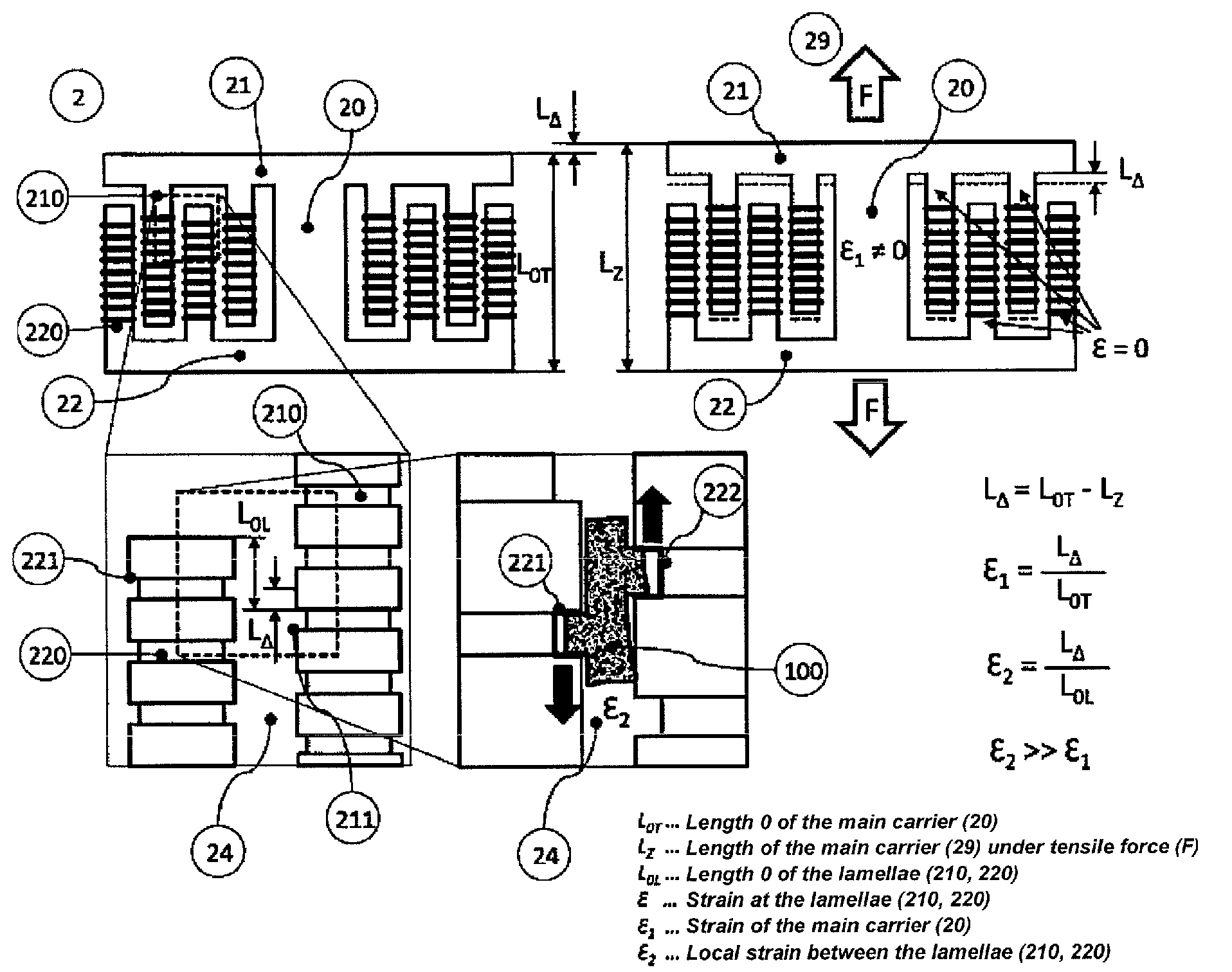
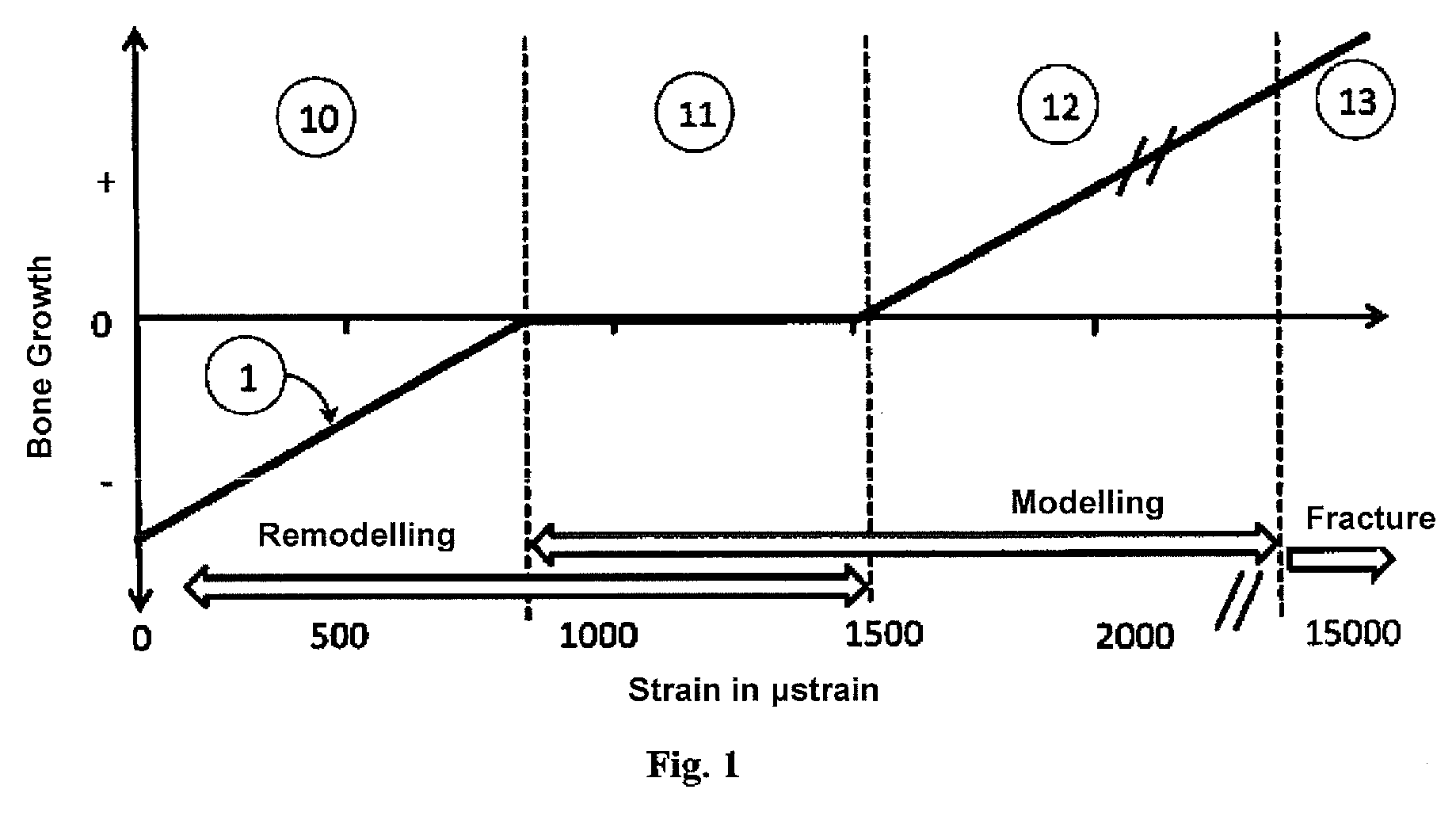
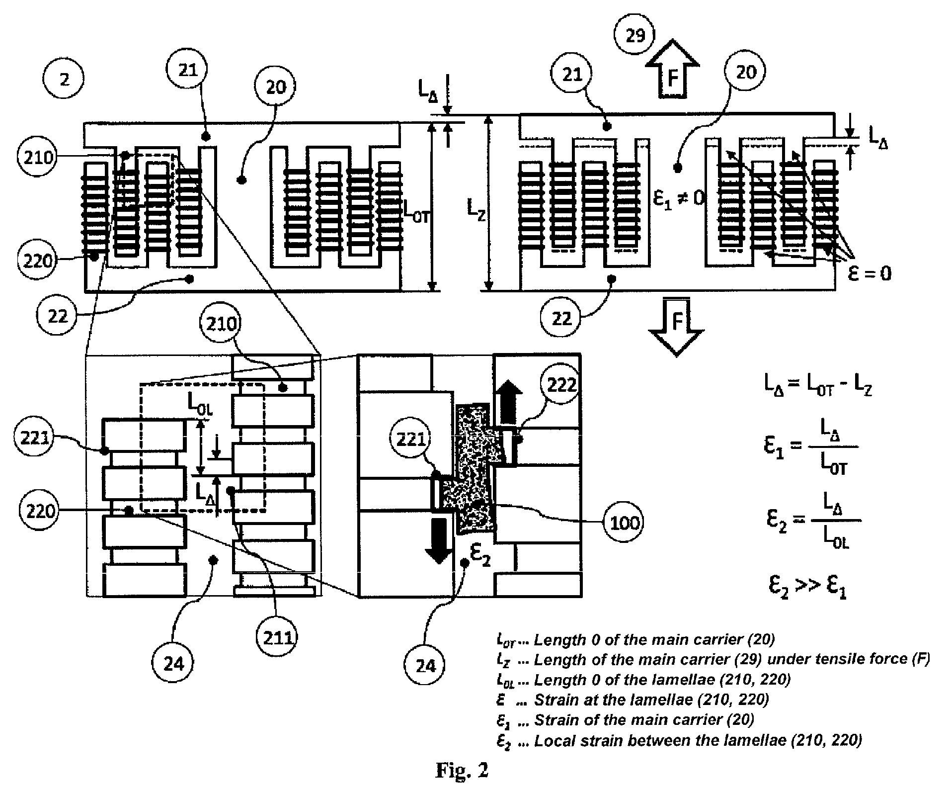
[0013]The object of the present invention is to provide an implant that can be connected to the bone in order to transmit loads and through a relative movement of suitable structures connected to the implant exerts a physiological strain stimulus on the tissue, with the aim of improving and / or accelerating the bone healing.

Technical Solution

[0014]This object is achieved in that lamella-like surface elements or structures (hereinafter also termed structure carriers) are arranged on the surface of an implant carrier. The structure carriers are largely decoupled from the implant carrier, but are connected at least at one point to the implant carrier, in particular in the region of the interfaces for the joining to the existing bone. In a preferred embodiment a plurality of structure carriers are in each case joined alternately to opposite sides of the interfaces of the implant carrier. The structure carriers can also contain depressions or openings (pores), in which the...


PUM

PropertyMeasurementUnit
structure sizeaaaaaaaaaa
forceaaaaaaaaaa

Abstract

The invention relates to an implant in the form of a bone-connecting device with an implant carrier, having at least two structure carriers for stimulating bone growth, the structure carriers can move relative to one another so that, due to a loading of the implant, a relative movement of the structure carriers occurs, the structure carriers furthermore contain structure elements that are arranged so that they define a plurality of partially open intermediate spaces, wherein a volume defined by these intermediate spaces and an immediate environment is deformed by the implant load, and a strain in the intermediate spaces and its immediate environment resulting from the deformation lies in the physiological range for bone growth.

Description

TECHNICAL FIELD[0001]The invention relates to an implant in the form of a bone-anchoring or bone-connecting device that can preferably be implanted to stabilise the spinal column. The implant can have a high intrinsic stiffness, which permits a dimensioning and design to provide high fatigue strength and implant durability. Due to the formation and arrangement according to the invention of surface structures on a structure carrier there can be generated—despite the high implant stiffness—a physiologically effective strain stimulus along the implant surface and between individual elements within the implant. The surface elements are dimensioned in such a way and are adapted to the load as well as stiffness of the implant so that a physiological strain stimulus, that is a strain stimulus that stimulates bone growth, is generated.PRIOR ART[0002]For surgical treatment, in particular in an osteosynthesis or stabilisation of spondylopathies, a large number of implants with screwable ancho...

Claims


Application Information

Patent Timeline
Patent Type & Authority Patents(United States)
IPC IPC(8): A61B17/84A61B17/86A61F2/44A61B17/80A61F2/30A61F2/28
CPCA61B17/84A61B17/80A61B17/8625A61B17/8685A61F2/44A61B17/864A61F2/4455A61F2002/286A61F2002/2835A61F2002/30563A61F2002/30565A61F2310/00796A61F2310/00976
Inventor HEUER, FRANKTRAUTWEIN, FRANKFRANKE, JORGPUTZIER, MICHAELKOTHE, RALPHMATGE, GUYLILJENQVIST, ULF
Owner ACES
Why Eureka
Try Eureka