System and method for producing a consistent quality syngas from diverse waste materials with heat recovery based power generation, and renewable hydrogen co-production

a technology of heat recovery based power generation and waste materials, which is applied in the direction of combined combustion mitigation, molten salt/metal gasification, sustainable manufacturing/processing, etc., can solve the problems of reducing the quality of waste-derived products, reducing the efficiency of waste-derived products, and reducing the cost of systems, so as to achieve the effect of processing more effectively and safely

Active Publication Date: 2016-04-19
RENEWABLE OPPORTUNITIES
View PDF1 Cites 13 Cited by
  • Summary
  • Abstract
  • Description
  • Claims
  • Application Information

AI Technical Summary

Benefits of technology

[0007]An embodiment of the present invention overcomes the heterogeneity of waste issues by focusing on wastes of known composition (e.g., weight / volume; chemical composition) that are used as feedstocks. This is accomplished by focusing on Industrial Solid Waste which is manifested to comply with EPA and U.S. Department of Transportation (DOT) regulations, focusing on specific waste streams (e.g., waste from paint manufacturers), as well as other known waste products (secondary materials). This specific knowledge of the waste materials that are used as feedstocks allows the waste to be processed more effectively and safely.
[0008]According to an aspect of the invention, the inventive process comprises the following steps: (a) tagging (e.g., barcode, quick response code, radio frequency identification tag [RFID]) of feedstock materials at the source concurrent with manifesting for transportation; (b) electronic sharing of manifest information by all parties involved with generating, transporting, and beneficial reuse; (c) leveraging tagged / manifest data to maximize processing efficiency, as well as environmental health and safety, while minimizing the risks inherent in chemical and physical variation in ‘unknown’ feedstocks; (d) loading of pumpable non-biodegradable feedstocks into a filtration system to remove unwanted particulates; (e) loading of non-pumpable non-biodegradable feedstocks into mechanical processing equipment for size reduction without decanting or other removal from shipping containers; (f) loading of biodegradable feedstocks into separate mechanical processing systems; and (g) slurification.

Problems solved by technology

One of the biggest barriers to the use of waste materials as a manufacturing feedstock is the diversity of the chemical composition, moisture content, and physical characteristics of waste materials.
Unlike fossil-based feedstocks (e.g., natural gas, coal) that have fairly consistent chemical composition and physical characteristics from one location to the next, waste materials are inherently diverse making the quality of waste-derived products more difficult to achieve.
Sorting and separating provides value in identifying wastes that have high energy value and desirable chemical compositions, but they are both capital and energy intensive, rendering the systems cost prohibitive.
Mixing waste provides a less expensive method for homogenizing the waste from one batch to another, but the potential for undesirable chemical reactions increases risks to human health and the environment.
However, there is opposing pressure from environmental protection priorities to reduce combustion stack emissions and greenhouse gas emissions.
The problem with conventional approaches is the persistence of an open-loop in the mass and energy balancing of the whole system.
Even though this can theoretically be solved using 100% renewable energy, the financial sustainability of the system becomes questionable due to the cost of utilities.

Method used


Image

  • System and method for producing a consistent quality syngas from diverse waste materials with heat recovery based power generation, and renewable hydrogen co-production
  • System and method for producing a consistent quality syngas from diverse waste materials with heat recovery based power generation, and renewable hydrogen co-production
  • System and method for producing a consistent quality syngas from diverse waste materials with heat recovery based power generation, and renewable hydrogen co-production

Examples


Embodiment Construction

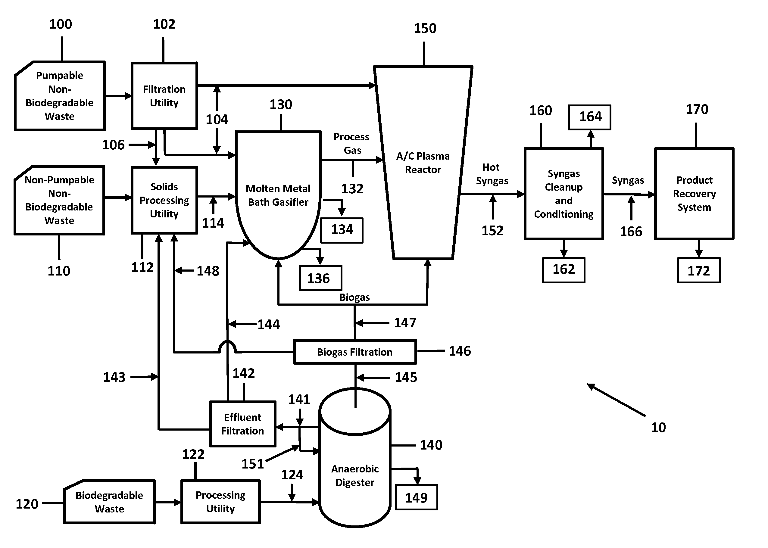
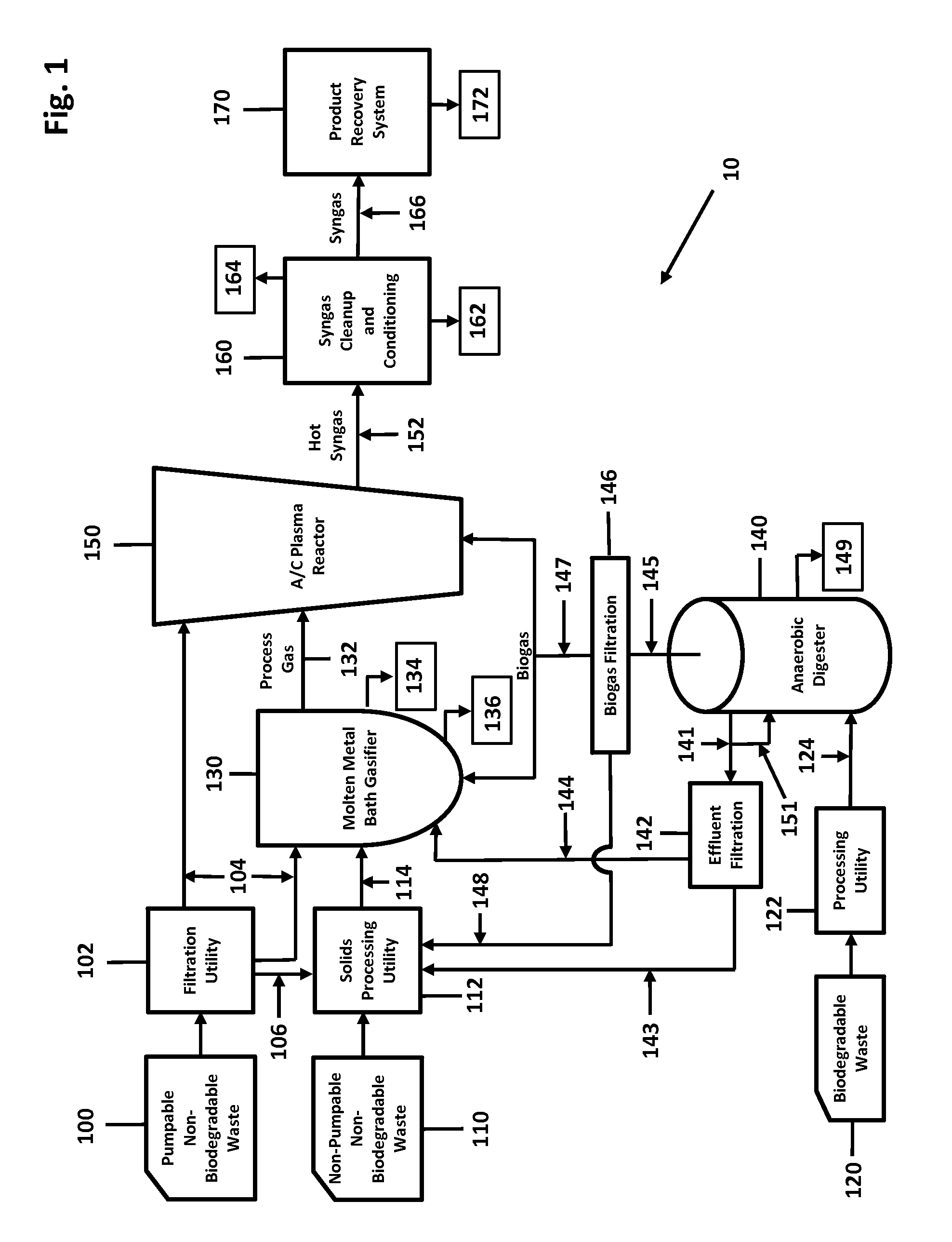
[0095]Referring now to FIG. 1, the presently preferred embodiment of the inventive system 10 begins with the acceptance of heterogeneous waste materials 100, 110, 120, which exclude, for example, Universal Wastes (see 40 CFR 273); explosives and munitions; radioactive materials; concentrated halogens and heavy metals. Waste products 100, 110, 120 received are identified (via electronic code, e.g., barcode, Quick Response Code, RFID, etc.) manually separated into three major categories for initial processing: 1) pumpable non-biodegradables 100; 2) non-pumpable solid / semi-solid materials, and any other non-liquid waste or secondary materials 110; and 3) biodegradables (e.g., plant, animal, and / or food industry waste) 120.

[0096]Biodegradable waste 120 is mechanically processed (shredding, grinding, milling, or other size reduction processes) by a biodegradables waste processing utility 122 to which water or other liquids are added as needed to produce a pumpable slurry 124 for input in...


PUM

PropertyMeasurementUnit
temperatureaaaaaaaaaa

Abstract

A system and method for converting waste and secondary materials into synthesis gas (syngas) through the use of a molten metal bath gasifier for the initial breakdown of waste feeds and an A / C plasma reactor for complete dissociation of waste feeds into syngas, and an anaerobic digester. The system includes a heat recovery and steam power generation process for the production of electricity. The system produces a net output of electricity above plant load sufficient for the co-production of renewable Hydrogen and Oxygen. The process does not require the use of fossil fuels or fossil feedstocks during normal operations, and it eliminates combustion produced stack emissions or landfill residuals.

Description

RELATED APPLICATIONS[0001]This application claims priority from U.S. Provisional Patent Application Ser. No. 61 / 794,471 filed on Mar. 15, 2013.BACKGROUND[0002]The beneficial reuse of waste materials has long been a priority in the protection of human health and the environment. More recently, attempts have been made to use a larger variety of waste as a manufacturing feedstock, primarily through the use of various gasification techniques.[0003]In the United States, the use of gasification technologies for waste disposal has been attempted with varying degrees of success since the 1970s. One of the biggest barriers to the use of waste materials as a manufacturing feedstock is the diversity of the chemical composition, moisture content, and physical characteristics of waste materials. This diversity is compounded by the variations in waste material from location to location, as well as changes in the characteristics of waste over time. Unlike fossil-based feedstocks (e.g., natural gas...

Claims


Application Information

Patent Timeline
Patent Type & Authority Patents(United States)
IPC IPC(8): C10B49/14C10J3/57B01J7/00C10G2/00C10L3/08C01B3/34
CPCC10G2/32C01B3/342C01B3/348C10L3/08C01B2203/04C01B2203/0405C01B2203/0415C01B2203/0465C01B2203/061C01B2203/062C01B2203/0833C01B2203/0861C01B2203/142Y02E50/343Y02E20/18C10G2/30Y02E50/10Y02E50/30Y02P30/00C01B3/32C07C29/1518C10L1/04C10L2290/04C10L2290/26C10L2290/38C10L2290/42C10L2290/547C12P5/023
Inventor COLE, RANDALLMURPHY, SETHBRUER, RONALDKAMINSKI, EDMUNDSACH, PETER
Owner RENEWABLE OPPORTUNITIES
Why Eureka
Try Eureka