Laser microcladding using powdered flux and metal

a technology of flux and powdered flux, applied in the field of metal joining, can solve the problems of limited hot box welding, inapplicability of many repair applications, and difficult welding of superalloy materials

Inactive Publication Date: 2016-04-19
SIEMENS ENERGY INC
View PDF17 Cites 9 Cited by
  • Summary
  • Abstract
  • Description
  • Claims
  • Application Information

AI Technical Summary

Problems solved by technology

It is recognized that superalloy materials are among the most difficult materials to weld due to their susceptibility to weld solidification cracking and strain age cracking.
However, hot box welding is limited by the difficulty of maintaining a uniform component process surface temperature and the difficulty of maintaining complete inert gas shielding, as well as by physical difficulties imposed on the operator working in the proximity of a component at such extreme temperatures.
However, this technique is not practical for many repair applications where the geometry of the parts does not facilitate the use of a chill plate.
These processes tend to trap the oxides (e.g. aluminum and chromium oxides) that are adherent on the surface of the particles within the layer of deposited material, resulting in porosity, inclusions and other defects associated with the trapped oxides.
The application of these processes is also limited to horizontal surfaces due to the requirement of pre-placing the powder.
Furthermore, because the protective argon shield tends to dissipate before the clad material is fully cooled, superficial oxidation and nitridation may occur on the surface of the deposit, which is problematic when multiple layers of clad material are necessary to achieve a desired cladding thickness.
For some superalloy materials in the zone of non-weldability there is no known commercially acceptable welding or repair process.
Furthermore, as new and higher alloy content superalloys continue to be developed, the challenge to develop commercially feasible joining processes for superalloy materials continues to grow.

Method used


Image

  • Laser microcladding using powdered flux and metal
  • Laser microcladding using powdered flux and metal
  • Laser microcladding using powdered flux and metal

Examples


Embodiment Construction

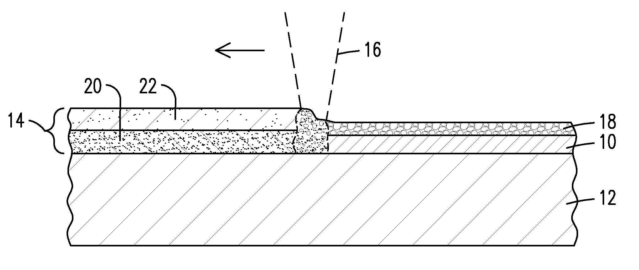
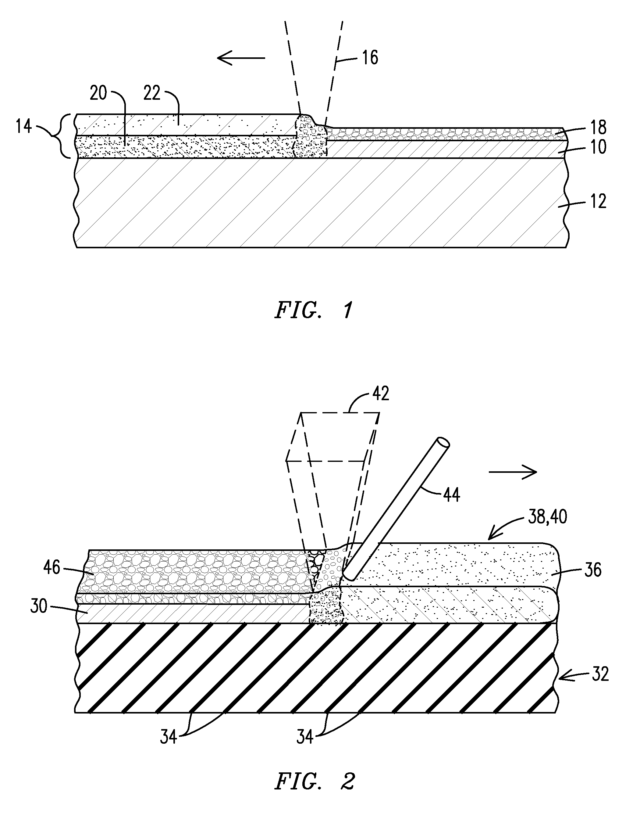
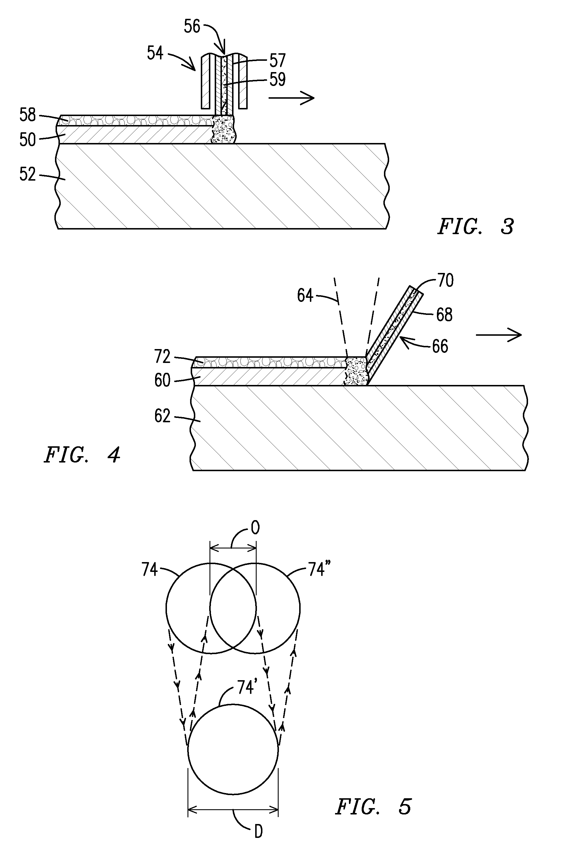
[0021]It is noted for the convenience of the reader that FIGS. 1-5 herein illustrate various aspects and applications of the inventive technology described herein, and that the description of FIG. 7 below is particularly directed to the use of the inventive technology for laser microcladding applications.

[0022]The present inventors have developed a materials joining process that can be used successfully to clad the most difficult to weld superalloy materials. While flux materials have not previously been utilized when welding superalloy materials, embodiments of the inventive process advantageously apply a powdered flux material during a laser microcladding process. The powdered flux material is effective to provide beam energy trapping, impurity cleansing, atmospheric shielding, bead shaping, and cooling temperature control in order to accomplish crack-free joining of superalloy materials without the necessity for high temperature hot box welding or the use of a chill plate or the ...


PUM

PropertyMeasurementUnit
temperatureaaaaaaaaaa
particle sizesaaaaaaaaaa

Abstract

A laser microcladding process utilizing powdered flux material (93b). A jet (92) of propellant gas containing powdered alloy material (93a) and the powdered flux material are directed toward a substrate (94). The powdered materials are melted by a laser beam (96) to form a weld pool (98) which separates into a layer of slag (100) covering a layer of clad alloy material (102). The flux material deoxidizes the weld pool and protects the layer of clad alloy material as it cools, thereby allowing the propellant gas to be nitrogen or air rather than an inert gas. In one embodiment, the substrate and alloy materials are superalloys with compositions beyond the traditional zone of weldability.

Description

[0001]This application is a continuation-in-part of pending U.S. patent application Ser. No. 13 / 005,656 filed on 13 Jan. 2011 (publication number US 2012 / 0181255 A1), incorporated by reference herein.FIELD OF THE INVENTION[0002]This invention relates generally to the field of metals joining, and more particularly to the welding clad buildup and repair of superalloy materials.BACKGROUND OF THE INVENTION[0003]Welding processes vary considerably depending upon the type of material being welded. Some materials are more easily welded under a variety of conditions, while other materials require special processes in order to achieve a structurally sound joint without degrading the surrounding substrate material.[0004]Common arc welding generally utilizes a consumable electrode as the feed material. In order to provide protection from the atmosphere for the molten material in the weld pool, an inert cover gas or a flux material may be used when welding many alloys including, e.g. steels, st...

Claims


Application Information

Patent Timeline
Patent Type & Authority Patents(United States)
IPC IPC(8): C23C24/00B23K26/073B23K10/02B23K9/32C23C24/10B23K9/04B23K26/34B23K15/00B23K26/32B23K35/02B23K35/32B23K35/28
CPCC23C24/106B23K9/044B23K9/324B23K10/027B23K15/0093B23K26/0732B23K26/082B23K26/144B23K26/32B23K26/322B23K26/34B23K26/342B23K35/0244B23K35/286B23K35/325B23K2201/001B23K2201/34B23K2203/50B23K2103/08B33Y70/00B33Y10/00B23K2101/001B23K2101/34B23K2103/50
Inventor BRUCK, GERALD J.KAMEL, AHMEDOTT, MICHAEL
Owner SIEMENS ENERGY INC
Why Eureka
Try Eureka