Adaptive AC power exchanger

a technology ac power exchanger, which is applied in the direction of dc-ac conversion without reversal, efficient power electronics conversion, climate sustainability, etc., can solve the problems of inability to adapt to the needs of ac power exchangers, inability to properly operate on 60 hz power, and patents that do not take into account, so as to improve the efficiency of inverters and reduce ripple currents , the effect of increasing

Active Publication Date: 2016-05-03
ADAPTIVE FREQUENCY HLDG
View PDF4 Cites 9 Cited by
  • Summary
  • Abstract
  • Description
  • Claims
  • Application Information

AI Technical Summary

Benefits of technology

[0017]An AC output bridge (inverter) is coupled to receive the first and second DC voltages. The AC output bridge includes a pulse-width modulation circuit for generating output AC having a zero voltage crossing relative to the second DC voltage; a load current limit circuit coupled to receive the output AC and limit the cycle-to-cycle frequency at the switching frequency of the pulse-width modulation circuit and generate a load current limit signal; an output LC filter with two inductors and a capacitor (hereafter referred to as “dual inductor LC filter”) coupled to the load current output AC, which includes a first inductor and a second inductor coupled in parallel with a bypass relay coupled to the parallel first and second inductors for decoupling the second inductor in response to an LC filter bypass control signal when the load limited AC current applied to a load is below a predefined level; and a load disconnect relay for disconnecting the load limited output AC from the load in response to a load disconnect control signal. In one embodiment, the AC output bridge generates 120 VAC, 60 Hz AC output power. The load disconnect relay provides surge protection for the plugged in appliance.
[0019]Therefore, in an exemplary adaptive AC power exchanger, a supply bias voltage (effectively + / −200 VDC) for the AC output bridge (inverter) that is more suitable for the 120 VAC output is provided. This is accomplished by a stacked (series) capacitor configuration at the output of the PFC circuit. With the mid-voltage (200 VDC referenced to the common connection) of the capacitor stack used as the output AC waveform “zero” crossing-voltage, the bridge is effectively biased with +200 VDC (400 VDC referenced to the +200 VDC mid voltage) for the positive half cycle of the output, and −200 VDC (referenced between the mid voltage and ground) for the negative half cycle. Consequently, without using more elaborate and costly circuitry, the inverter is biased with lower and more desirable voltage levels to improve the efficiency of the inverter.
[0020]With respect to the two inductors of the output filter of the inverter, at light loads a higher value inductance is used to reduce the ripple currents. However, this higher value inductance functioning at the rated output current will necessarily require a substantially larger and heavier inductor. Consequently, a lower value inductor with a higher current capacity is switched on by the inductor bypass relay to increase the total current capacity of the parallel inductors comprising the output filter. A significant benefit of this parallel inductor arrangement with the bypass relay is that the high surge current to start some appliances will not exceed the capacity of the output inductors. Without this arrangement, the inductors would saturate resulting in very high peak currents (that do not flow to the load but are circulating internally), which risks catastrophic failure of the inverter. Because it is not predictable what a consumer will try to connect to the inverter output, the parallel inductor / bypass relay arrangement minimizes the risk of such a failure by increasing the capacity of the inductor currents without excessively increasing the size of the output filter inductors.
[0023]Another aspect is the incorporation of power factor correction or in the case of a photovoltaic array embodiment, bidirectional power factor correction, which causes the current waveform to follow the AC input voltage waveform so as to achieve a power factor of approximately one. Power factor correction has a positive impact on the power grid by providing power to the adaptive AC power exchanger with reduced power distribution losses in the grid, which effectively increases the capacity of the grid. Furthermore, any appliance powered by the adaptive AC power exchanger, will reflect / acquire the near unity power factor of the adaptive AC power exchanger as viewed from the grid, or in another perspective, will act as a harmonic filter eliminating the inefficiencies and losses caused by harmonics induced on the grid. This is significant with many utility providers where regulations require that the appliances be designed with higher power factor correction to prevent grid power losses and maximize the delivery of useful power. Using this adaptive AC power exchanger satisfies the requirements of many utility providers outside of North America. In other words, an appliance which would not otherwise meet regulatory requirements regarding power factor correction in countries outside North America would appear to the grid to be power factor corrected and hence compliant when powered through the described adaptive AC power exchanger.
[0025]In still another embodiment, the adaptive AC power exchanger can incorporate an information management capability that may include remote communication capability. Specifically, because the power adaptive AC power exchanger is connected between the load (e.g., appliance) and the grid, information such as electricity usage, cost of operation of the appliance, times of usage, and other information can be obtained and transmitted through Bluetooth, Wi-Fi, or other communications means to remote receivers such as smart phones and the like to thereby enable the consumer to monitor the functioning and performance of the connected appliance remotely. The consumer then can devise schemes to utilize the appliance at certain times to save on energy cost. In yet another embodiment, the power and system monitor can be coupled to the AC output controller so that the user can modify the AC output controller program or correct firmware bugs and thereby remotely change the functioning of the adaptive AC power exchanger.

Problems solved by technology

Consequently, appliances which are made to operate on 60 Hz power will not function properly if the power is a different frequency such as 50 Hz.
However, that patent did not take into account the reality of the variable frequency and voltage of the typical international power source and specifically the need to accept power from a power source that varied unpredictably, for example, around a 220 VAC nominal characteristic.
Conventional converters are inherently large and bulky and are ill-suited for consumer applications.
Also, consumer environments are subject to contamination by moisture (humidity), dust, lint, articles of clothing and the like that can seriously degrade the performance of the adaptor electronics, particularly in compact environments.
Such sealing precludes the use of internal fans for cooling, a conventional approach to cooling converters.
In many environments, the conventional converter had to function reliably in high ambient temperature conditions thereby requiring noisy, robust active cooling systems.
Such approaches are incompatible with the requirements of consumer adaptors particularly where such adaptors are in enclosed or sealed environments where cooling is limited to reliance on passive cooling.
The restoration of power may result in power surges that can cause damage to any connected appliance.
Using conventional electronics in the consumer environment and applications described, additional problems arise that contribute to inefficiencies.
However, the suitable VDC for 120 VAC output is only 200 VDC.
To provide 400 VDC will cause high circulation current on the circuit inductors and capacitors, which will produce switching loss and conduction loss.
The high no load loss is a serious energy loss for home application as the load level would likely be very low most of time.
A second problem is high power losses when the load level is high.
Higher voltage IGBTs and MOSFETs result in conduction and switching losses in high current (high load) applications.
The high inductance inductors also have high resistance resulting in high power losses in high load applications.
A third problem relates to high surge current loads, which can occur when high load appliances such as refrigerators, air-conditioners, vacuum cleaners and the like are attached.
In such applications, the peak current on the inductors in response to the high surge current will cause saturation of the inductors, which in turn causes loss of inductance rendering the circuit vulnerable to damage.
A fourth issue relates damage that can occur in abnormal circumstances where a high DC voltage passes through the converter to the output, which can cause damage to the connected appliance (load) itself.
With respect to the above-described switching losses and ripple currents when the output AC bridge is biased with voltages that are higher than the requirements of a 120 VAC output, if an unnecessarily high voltage is used to bias the inverter (for example the 400 VDC from the PFC circuit) to create the 120 VAC output, the ripple currents increase in the inductors and capacitor of the inverter filter resulting in conduction losses.
Higher voltages also increase switching losses.
However, this higher value inductance functioning at the rated output current will necessarily require a substantially larger and heavier inductor.
Without this arrangement, the inductors would saturate resulting in very high peak currents (that do not flow to the load but are circulating internally), which risks catastrophic failure of the inverter.

Method used


Image

  • Adaptive AC power exchanger
  • Adaptive AC power exchanger
  • Adaptive AC power exchanger

Examples


Embodiment Construction

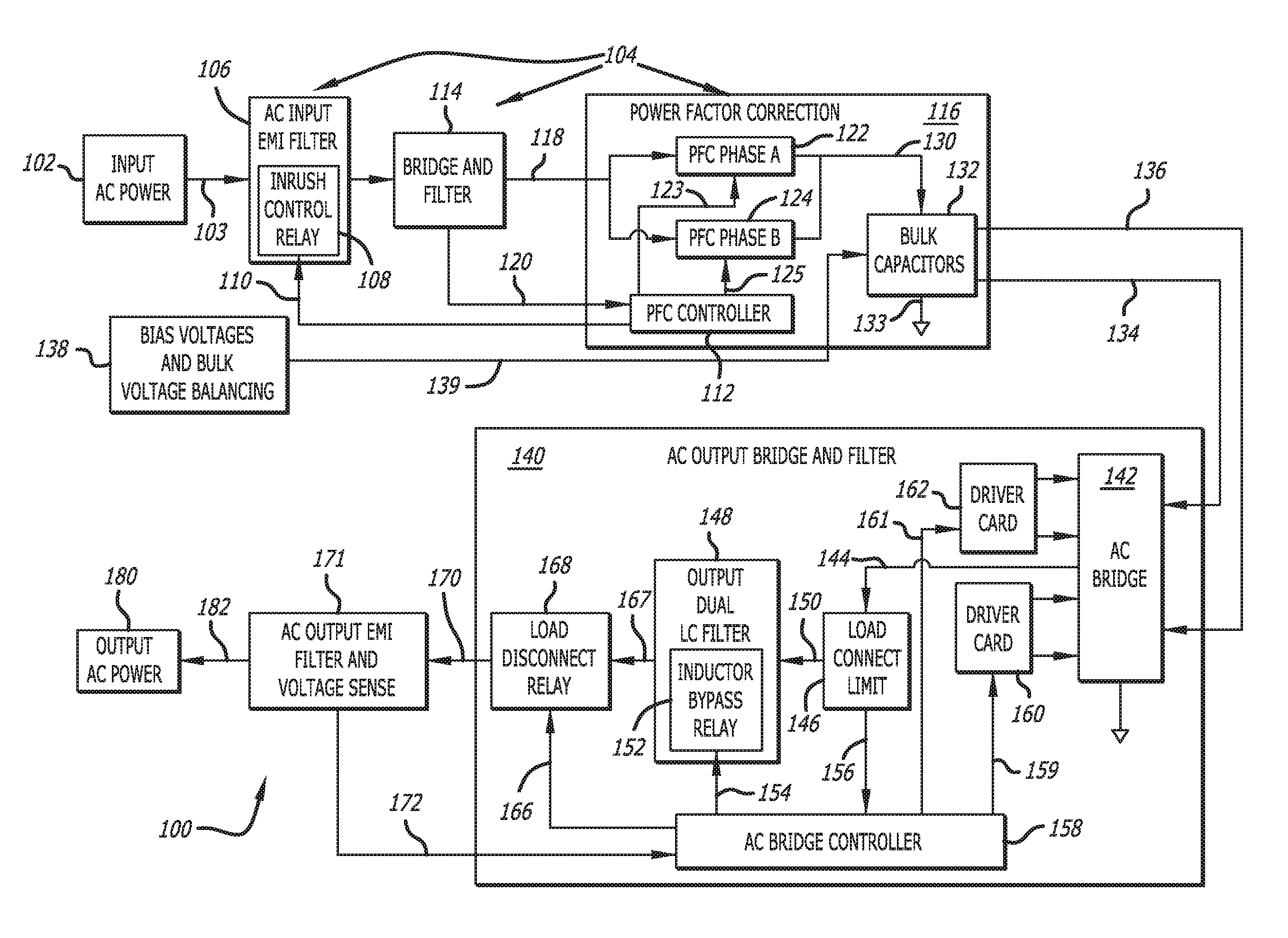
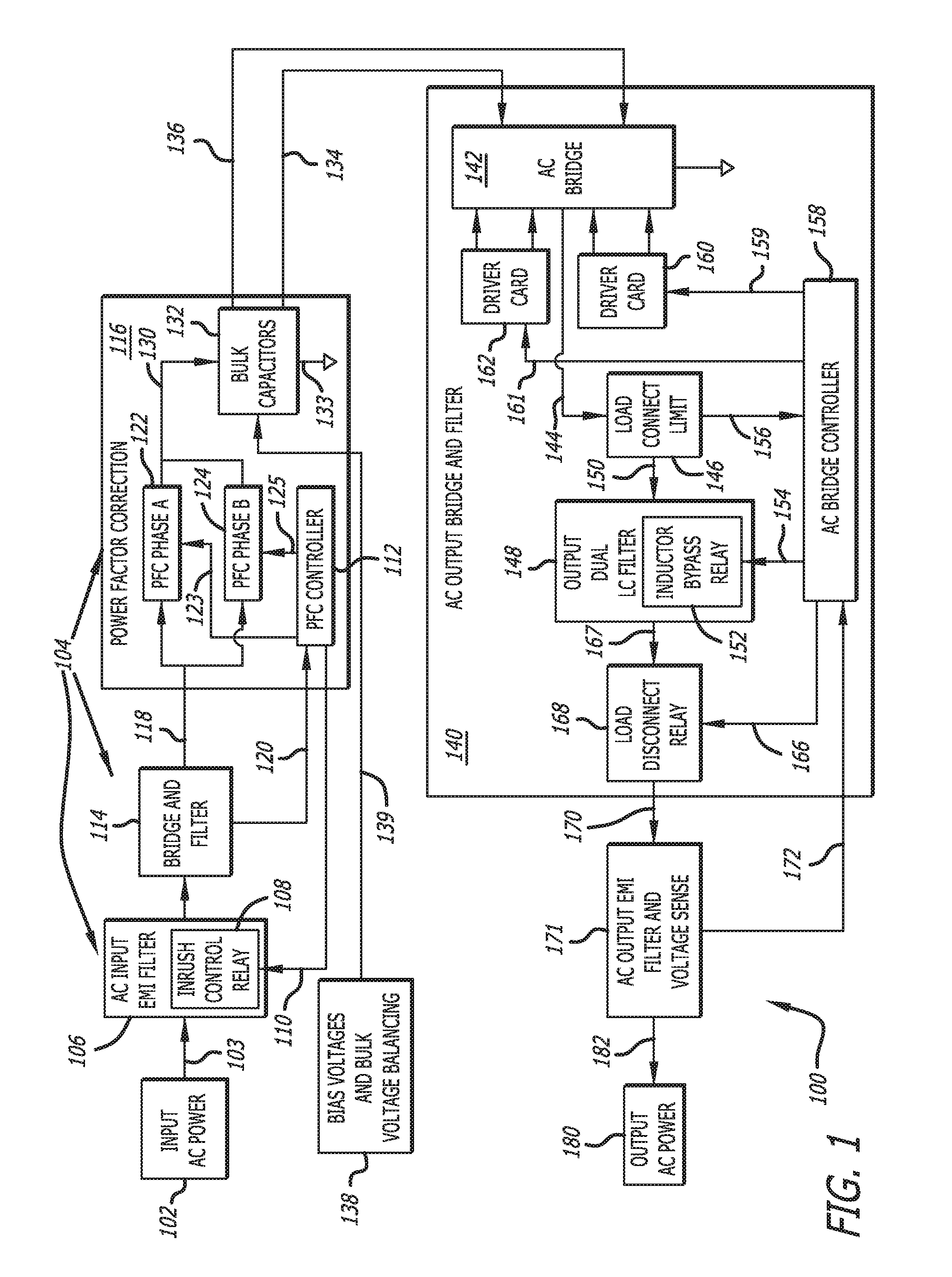
[0033]Referring to FIG. 1 in conjunction with the specific circuit embodiment shown in FIGS. 3-5, an adaptive AC power exchanger system 100 is coupled between an AC source 102 and a load 180 such as a home appliance. The AC source 102 may be a connection to a utility grid which, in the embodiment illustrated hereafter, will generally provide 220 VAC, 50 Hz power although the power may vary in both frequency and voltage over time. For example the voltage may vary from 180 VAC to 280 VAC and frequency from 40-60 Hz. Furthermore, the AC power provided on the grid by the utility may be intermittent.

[0034]The load 180 will generally be an appliance with motors, servos and the like as well as timing circuitry to control the sequence and timing of the motors and servos of the appliance. The power to drive those appliances must be substantially stable, in the embodiment illustrated, will be 120 VAC, 60 Hz. Accordingly the adaptive AC power exchanger must be able to accept power with variabl...


PUM


Abstract

An adaptive AC power exchanger generates stable 120 VAC 60 Hz power from variable grid input power nominally at 220 VAC and 50 Hz. The exchanger includes an AC-DC circuit stage coupled to receive the input AC current and generate a VDC output, and a DC-AC circuit stage to generate power for a load. The AC-DC stage includes an EMI filter and surge protection circuit, a 50 Hz rectifier and a power factor correction (PFC) circuit controlled by a PFC controller to yield a 400 VDC output coupled through a bulk capacitor stack to a common connection to generate a 200 VDC voltage node. The 200 VDC and 400 VDC voltages are coupled to the DC-AC circuit including a pulse width modulator; current load limiter; an LC filter having a capacitor, dual inductors and an inductor by-pass relay; and a load disconnect relay all controlled by an AC bridge controller.

Description

RELATED APPLICATIONS[0001]This application claims priority based on U.S. Provisional Application No. 62 / 117,615, which was filed Feb. 18, 2015. This application also claims priority based on the U.S. Utility application Ser. No. 14 / 723,108, which was filed May 27, 2015.BACKGROUND[0002]1. Field[0003]Electrical power conversion and more specifically an AC power exchanger that can adapt to the variable voltage and frequency characteristics from an electrical power grid source and generate a stable power output that could be used to power common household appliances designed to operate at the output power.[0004]2. General Background and State of the Art[0005]Many appliances such as washing machines, dryers, dishwashers and the like required generally stable power source, which in the United States would 120 VAC, 60 Hz power. This arises at least in part because the timing mechanism of the appliance is dependent on the frequency of the electrical power used to control the appliance. For ...

Claims


Application Information

Patent Timeline
Patent Type & Authority Patents(United States)
IPC IPC(8): H02M1/42H02M1/44
CPCH02M1/42H02M1/44H02M5/4585H02M7/48H02M1/10H02M1/126H02J3/1828Y02E40/30H02J2300/24H02J3/381Y02E10/56Y02B70/10
Inventor BANAYAN, AZIZLIU, CHENG-PINWHITE, ROBERTFLAVIN, JOHN
Owner ADAPTIVE FREQUENCY HLDG
Why Eureka
Try Eureka