
Laser cutting strengthened glass

a technology of reinforced glass and laser cutting, which is applied in the direction of manufacturing tools, door/window protective devices, instruments, etc., can solve the problems of reducing the efficiency and throughput of such commercial processes, and processing multiple glass sheets or substrates can be particularly difficul

Active Publication Date: 2016-11-01
KINESTRAL TECH
View PDF20 Cites 59 Cited by
  • Summary
  • Abstract
  • Description
  • Claims
  • Application Information

AI Technical Summary

Problems solved by technology

Processing many different sizes of glass sheet is less desirable for certain commercial applications, however, because machinery and applications may need to be customized for different sizes of glass sheet.
Processing different sizes of glass sheets also decreases the efficiency and throughput for such commercial processes.
Processing multiple sizes of glass sheets or substrates can be especially challenging for processes which include depositing coatings on the glass substrates such as vacuum sputtering, dip coating, or slot die coating.
Additionally, processing glass prior to strengthening increases the chances of the glass breaking during earlier processing steps.
Despite such shortcomings, however, the art has not heretofore developed commercially meaningful glass fabrication approaches which would allow preparing and processing thermally strengthened glass in standardized, large-scale format with subsequent cutting to custom sizes for particular applications.
In addition to the common industry understanding that cutting processes do not work for thermally strengthened glass, some industrial applications have additional technical challenges which make such an approach less certain.
For example, coating glass substrates with thin films prior to strengthening may be undesirable for applications that include films that may be altered by process conditions associated with strengthening (e.g., where films may not withstand the temperatures used for thermal strengthening the glass).
Methods for cutting chemically-strengthened are known but typically have resulted in cut glass substrates with unacceptable edge defects.
These edge defects are unacceptable for many applications because they greatly reduce the overall strength of the cut glass and can serve as nucleation points for larger cracks.
These mechanical steps produce particles that are unacceptable for many applications.
Notably, for example, the generated particles can cause damage to the surface of the glass and coatings formed on the surface of the glass.
(“Kwak et al.”) acknowledges that tempered glass cannot be cut and that electrochromic devices cannot withstand the process conditions required to temper the glass.
However, the resultant device does not meet the strength requirements for many applications unless a very low thermal expansion glass such as borosilicate glass is used, and borosilicate glass is very expensive relative to other types of glass such as soda-lime glass.
This method typically produces undesirable cracks and debris, and because of the relatively wide heat affected area, the kerf width is not negligible.
These drawbacks have prevented the successful application of this type of method to cutting strengthened glass.
Relying on the propagation of a crack along a defect line is not preferred for cutting strengthened glass and especially for thermally strengthened glass, because cracks may propagate uncontrollably or simply reduce the strength of the cut edge making the cut piece of glass unusable.
However, cutting thermally-strengthened glass is different from and significantly more difficult than cutting chemically strengthened glass (e.g., due to different compressive and tensile stress properties) and no details on the laser process conditions, evidence, or examples of cutting thermally-strengthened glass are provided.
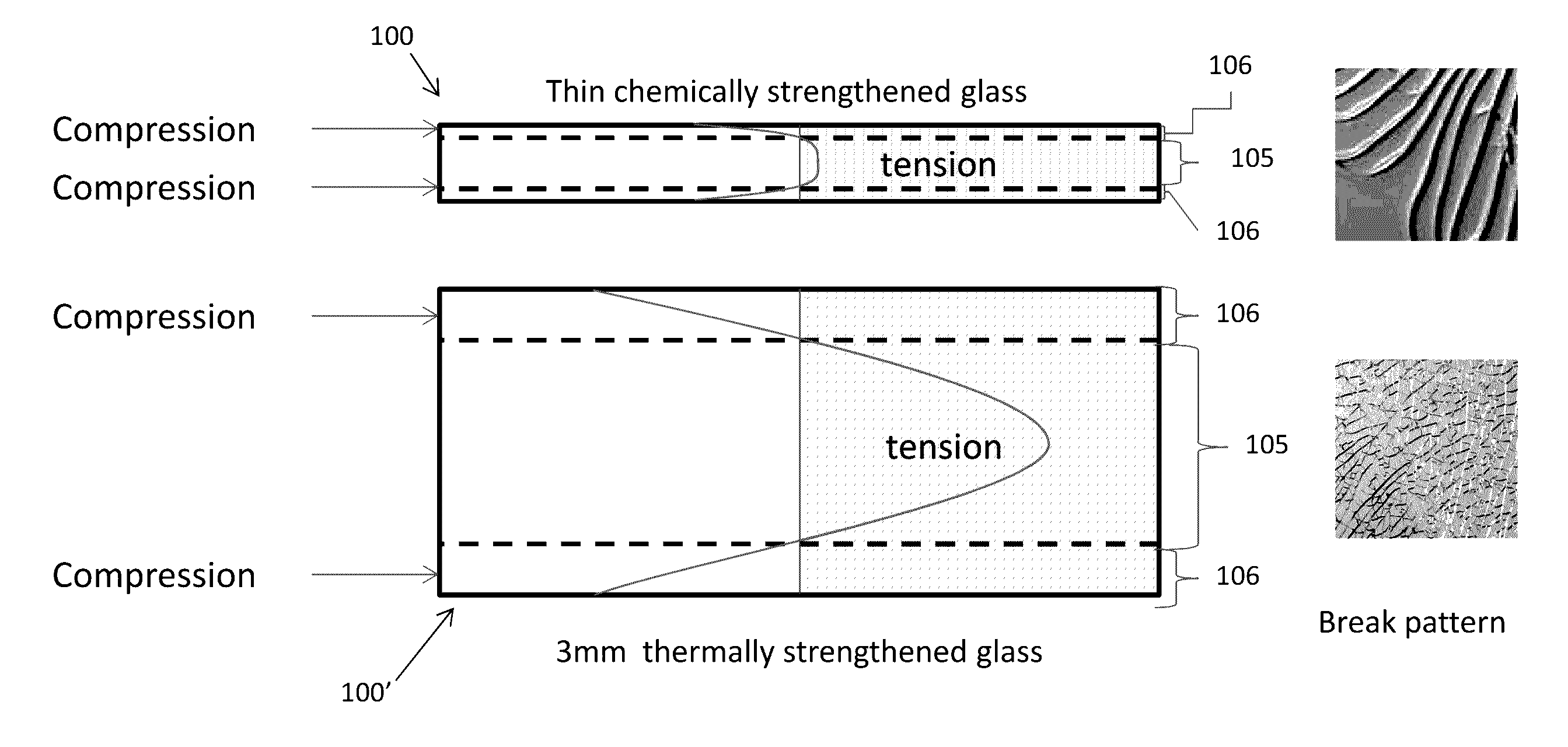
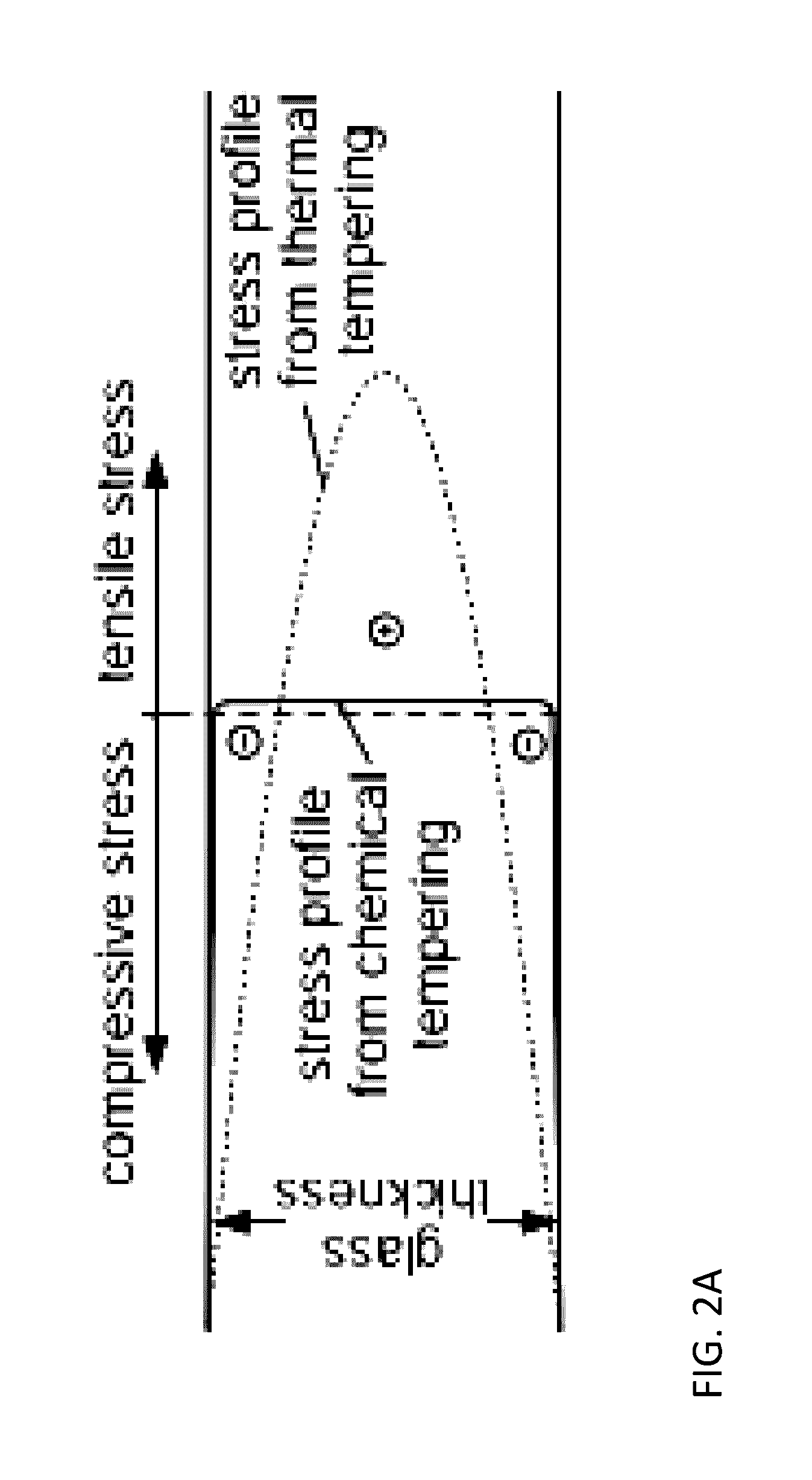
In fact, the disclosed approach would not be successfully applied to thermally-strengthened glass because the tensile stress in the center region of thermally-strengthened glass is much higher and defects or laser induced damage in this region could cause the glass to explode into small fragments.
In addition, the propagation of a crack through thermally-strengthened glass would be much harder to control as the mean free path of crack propagation is much smaller than in chemically strengthened glass and the total stored energy is much greater.
Finally, even if the laser induced damage line method occasionally yields successfully cut thermally-strengthened glass, the edges created by the crack propagation would be overpopulated with many micro cracks that would greatly reduce the strength of the cut glass and prevent it from passing standard ASTM strength tests required for building and transportation applications.
For laser ablation techniques, using a CO2 laser for example, the heat affected zone is quite large and would not be useful for cutting strengthened glass as the strain created by the heat would cause the glass to break.
In order to do this, the laser is focused in the region of the glass under tensile stress and the energy provided by the laser is converted to thermal energy and locally modifies the glass thus creating a defect.
Higher CTE glass would be expected to be much more difficult to cut using this method because the strain induced by the local heating could be enough to initiate the propagation of a crack in the tensile region of the glass, where Harvey et al. claims should be the location of the laser induced damage line.

Method used


Image

  • Laser cutting strengthened glass
  • Laser cutting strengthened glass
  • Laser cutting strengthened glass

Examples


example 1

[0159]A glass substrate for use in a window is first heat strengthened to reach the necessary surface stress for the final window product. In most cases a surface stress of around 65 MPa is sufficient but this can vary depending on the installation location and other factors. The glass substrate is then coated with a first layer of an electrochromic film. The first layer of the electrochromic film can be cured at a temperature of less than 300° C. Some processes do not require a cure post coating, for example sputtered electrochromic layers do not typically require a thermal treatment after deposition. In parallel, a matching counter electrode electrochromic layer is coated on another strengthened glass substrate of equal size to the first glass substrate. The counter electrode electrochromic layer may be cured or not cured.

[0160]The two coated strengthened glass substrates are then laminated together with a polymer between the two glass substrates which has the necessary ion conduc...

example 2

[0162]A soda-lime glass substrate is provided. The soda-lime glass is processed to add a transparent conducting oxide (TCO) layer during the thermal-strengthening process. The soda-lime glass undergoes a custom high temperature TCO process where the glass reaches a temperature of around 650° C. The substrate is subsequently cooled at a rate that induces a surface stress of around 60 MPa. The TCO-coated, heat-strengthened glass is then coated with an electrochromic coating and calcined at a temperature of around 300° C. for around 1 hour.

[0163]The thermally-strengthened glass substrate can then be assembled into a large device with a strengthened glass pair using a polymer ion conductor between the two pieces of strengthened glass. The assembled device is then cut down into the desired smaller device sizes using the laser filamentation processes described herein.

example 3

[0164]A 3.2 mm soda-lime glass substrate from Pilkington (TEC-15 TQ) is cleaned, heat-strengthened or tempered and then cleaned again. After cleaning, the substrate is coated with a cathode solution using slot-coating, spray coating, or dip coating. The wet coated cathode film is subsequently dried using air, heating, vacuum, or a combination or sequence of these methods. After the film is dried the cathode film is heated to a temperature between about 250° C. and about 550° C. in a controlled environment, e.g. clean dry air, to create the desired cathode material.

[0165]A second 3.2 mm soda-lime glass substrate from Pilkington (TEC-15 TQ) is cleaned, heat-strengthened or tempered and then cleaned again. After cleaning the substrate is coated with an anode solution using slot-coating, spray coating, or dip coating. The wet coated cathode film is subsequently dried using air, heating, vacuum, or a combination or sequence of these methods. After the film is dried the cathode film is he...


PUM

PropertyMeasurementUnit
wavelengthaaaaaaaaaa
speedaaaaaaaaaa
thicknessaaaaaaaaaa

Abstract

Methods for cutting strengthened glass are disclosed. The methods can include using a laser. The strengthened glass can include chemically strengthened, heat strengthened, and heat tempered glass. Strengthened glass with edges showing indicia of a laser cutting process are also disclosed. The strengthened glass can include an electrochromic film.

Description

RELATED APPLICATIONS[0001]This application claims priority to U.S. Provisional Patent Application Ser. No. 61 / 794,546, filed on Mar. 15, 2013, the disclosure of which is incorporated herein by reference in its entirety for all purposes. In addition, all publications and patent applications mentioned in this specification are herein incorporated by reference to the same extent as if each individual publication or patent application were specifically and individually indicated to be incorporated by reference.FIELD OF THE DISCLOSURE[0002]The present disclosure and inventions relate generally to methods for cutting strengthened glass, such as thermally strengthened glass, to methods for fabricating electrochromic composites, to methods for fabricating electrochromic devices, and to methods for fabricating insulated glass units. The disclosure and inventions also relate to cut thermally strengthened glass, to electrochromic composites, to electrochromic devices and to insulated glass uni...

Claims


Application Information

Patent Timeline
Patent Type & Authority Patents(United States)
IPC IPC(8): B23K26/00E06B3/66B23K26/38C03B33/09B23K26/40G02F1/153
CPCC03B33/091B23K26/38B23K26/40E06B3/66G02F1/1533B23K2203/50Y10T428/24777B32B17/10036B32B17/10155B32B17/1055B32B17/1077B23K26/0624B23K26/361B23K2103/50B23K2103/54C03B33/0222Y02P40/57B23K26/402E06B3/663E06B3/673E06B9/24E06B2009/2464
Inventor BERGH, HOWARD STIMMERMAN, NICOLAS
Owner KINESTRAL TECH
Learn More