Waste heat recovery and optimized systems performance

a technology of waste heat and system performance, applied in the field of waste heat recovery, can solve the problems of waste heat simply becoming waste heat, cooling generates considerable quantities of heat, etc., and achieves the effect of reducing energy consumption

Active Publication Date: 2017-07-11
AMERICAN INNOVATION CORP
View PDF12 Cites 11 Cited by
  • Summary
  • Abstract
  • Description
  • Claims
  • Application Information

AI Technical Summary

Benefits of technology

[0006]In air conditioning and refrigeration systems, considerable energy savings is possible by rejected (waste) heat recovery using heat pipe condensers (Heat Pipe Heat Exchangers) in all condensers of the systems.
[0012]As in conventional heat exchangers, fins may be added to the external surface of the heat pipes to increase the effective surface area. However the contribution of fins in augmenting the heat transfer area must be balances against the heat pipe group weight. Since it is not necessary to intersperse the cold and hot side flow streams in a heat pipe heat exchanger, heat transfer is accomplished with little or no disruption or diversion of the flow streams. Inlet and outlet flow distribution plenums will be considerably simplified or may not be needed at all. Complete separation of the fluid streams like in the case of multiple separate type heat pipe heat exchanger can be particularly advantageous when the hot and cold side fluids are chemically reactive, and mixing of the streams in the event of leak must be avoided. The heated pipes in a heat pipe heat exchanger are arranged in stages, each stage consisting of a single row of heat pipes, all of which are of the same temperature. The heat pipe temperature changes from stage to stage, varying from a minimum value at one end of the heat pipe heat exchanger to a maximum value at the other end. If a temperature range is large enough, more than heat pipe fluid could be required to ensure adequate heat transport capability in all stages. The required heat transfer area for a given heat transfer rate decreases as the number of stages is increased, but the pressure drop of the hot and cold side fluids also increases with the number of stages. Therefore pressure drop limitations may establish the maximum number of stages and the minimum heat transfer area.

Problems solved by technology

Cooling generates considerable quantities of heat, if not utilized, this energy simply becomes waste heat.

Method used


Image

  • Waste heat recovery and optimized systems performance
  • Waste heat recovery and optimized systems performance
  • Waste heat recovery and optimized systems performance

Examples


Embodiment Construction

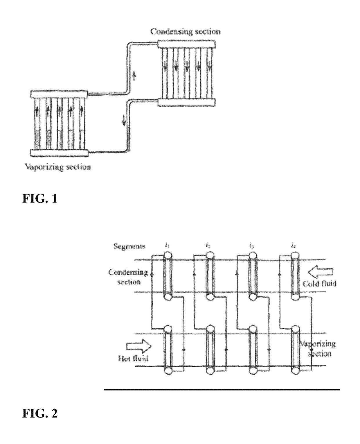
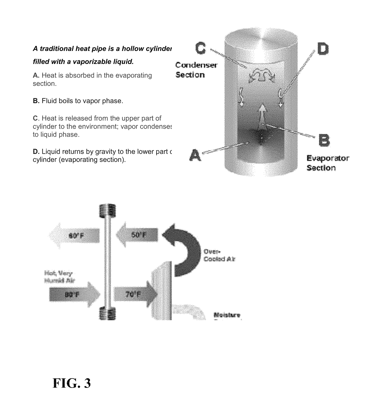
[0039]The invention relates to improving the efficiency of waste heat recovery of large scale refrigeration and air conditioning systems. This also can be applied to other industrial systems in different applications that use heat rejected in the process. The heat rejected in any process to a coolant is mainly can be considered waste heat unless it is recovered from a heat pipe condenser or heat pipe heat exchanger or used in other process or saved any form of energy. In the refrigeration system with hot gas diversion of FIG. 6

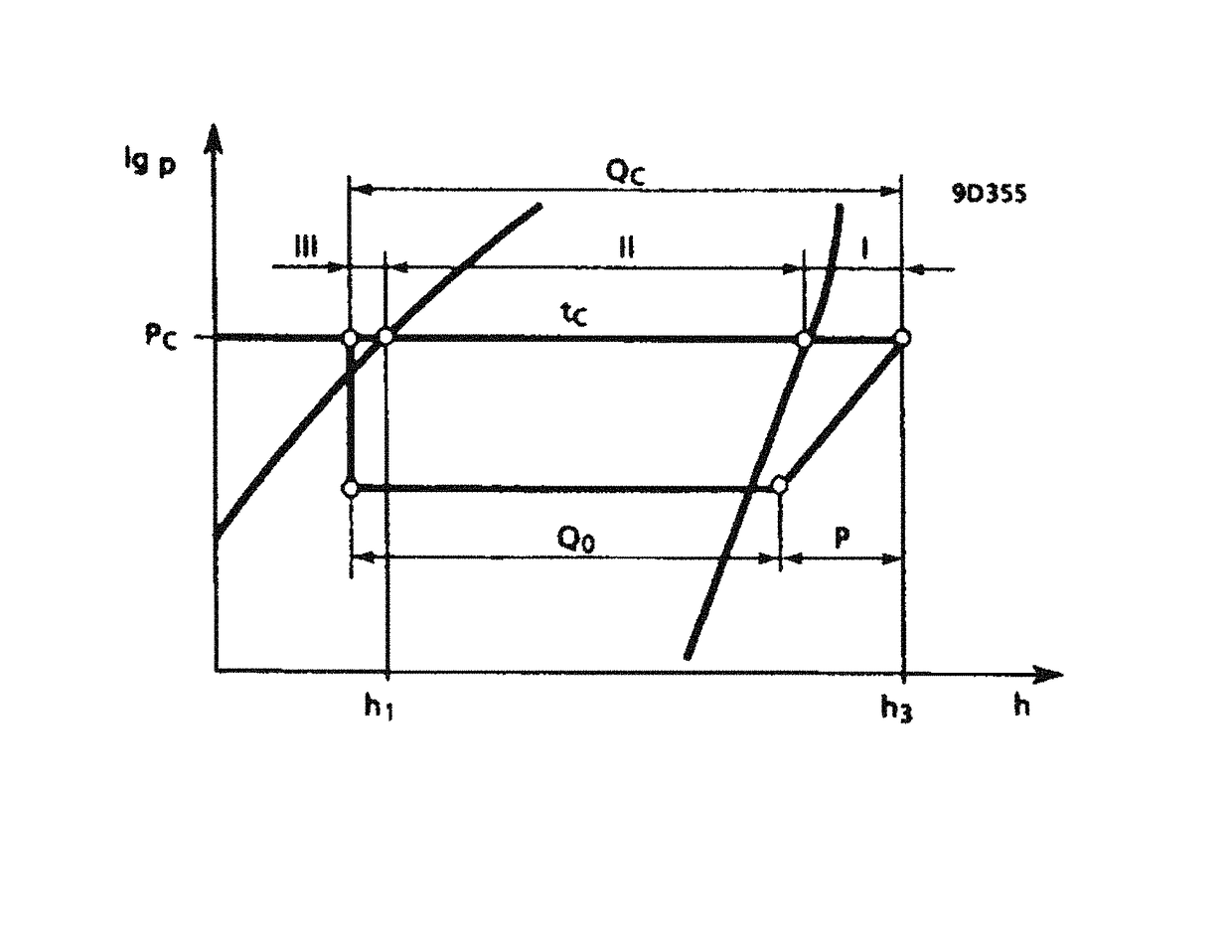
Heat Supply of the Condenser:

[0040]The heat absorbed in the evaporator Qe and the compressor P in the form of heat must be released again in the heat pipe condenser. Instead of dissipating this heat quantity Qc to the environment, appropriate measures can be implemented in order to put the heat flow to meaningful use for heating purposes because of the temperature level. The condenser's output Qc depends mainly on the refrigerant volume V circulated per unit t...


PUM


Abstract

Energy systems in different industrial applications including automotive applications experience between 20 to 50 percent of raw energy input as waste heat. in the form of hot exhaust gases, hot cooling water and lost heat from hot equipment surfaces including heated products. Continued efforts to improve systems energy efficiency, recovering waste heat losses provide attractive opportunities for reduced emission and less costly energy resources. This invention introduces other methods for higher performance of existing energy consuming systems by optimizing the performance of some of the system modules that contributes to the waste energy. in turn reduce energy consumption of these systems, reduces its operating cost, damages to the population health by reducing pollution improving the environment quality, and also reduces the cost of health care. Improving efficiency of the module's' which contribute large percentage of waste energy as by-product from the operation of these systems can improve the system efficiency.

Description

BACKGROUND OF THE INVENTION[0001]Field of the Invention[0002]The invention disclosure relates to waste heat recovery to put excess heat to work, providing warmth to buildings or steam or process heating for chemical processing industry. Conserve valuable energy by extracting thermal energy from a waste stream and putting it to work in traditional design of operable energy systems in different applications and configurations, like refrigeration and air conditioning systems, internal combustion engines in automobiles, internet data centers, reversible waste heat recovery from some system energy consumption in agriculture for converting waste material into fuel and other useful products, and many other Industrial applications that generate waste heat as by-product. Using heat pipe technology in an innovative way in applications where waste heat recovery can provide additional substantial economical savings to the system operation. More efficient energy recovery by minimizing the delta ...

Claims


Application Information

Patent Timeline
Patent Type & Authority Patents(United States)
IPC IPC(8): F28D15/02F25B39/00F24F13/30F24F12/00F24H4/02F28D21/00F25B39/04
CPCF24H4/02F25B39/00F24F12/00F28D15/0266F24F13/30F24F12/001F28D15/02F25B39/04F25B2339/042F28D2021/0063F24F2012/005F25B6/02F25B6/04F25B7/00F25B30/02F25B2339/047F28D21/0014Y02B30/56
Inventor MANKARUSE, NAGUI
Owner AMERICAN INNOVATION CORP
Why Eureka
Try Eureka