Method and apparatus to coat a metal implant with electrospun nanofiber matrix

a technology of electrospun nanofibers and metal implants, which is applied in the field of polymer fiber production, can solve the problems of economic burden, further implant loosening and eventual implant failure, and limited use of pcl-enf matrix as a coating material for implants, and achieves enhanced fiber diameter in pcl-cg nfm at the groove of ti on the ti-bone interaction, and improved bonding.

Active Publication Date: 2017-11-07
UNIVERSITY OF CENTRAL OKLAHOMA
View PDF79 Cites 11 Cited by
  • Summary
  • Abstract
  • Description
  • Claims
  • Application Information

AI Technical Summary

Benefits of technology

[0008]The present invention implements a set of grooves / ridges that are created on titanium (Ti) at the circumferential direction to increase the surface area of implant in contact with bone. These grooves / ridges protect the nanofiber matrix (NFM) made with Polycaprolactone (PCL) electrospun nanofiber (ENF) and collagen (CG) at the groove from physiological loading.
[0009]The present invention provides controlled fabrication of a microgrooves made with machine sawing, laser indentation, and titanium nitride (TiN) ion deposition around the circumference of Ti using a plasma nitride deposition technique. PCL ENF may be deposited along the sub-micrometer grooves with the help of plasma oxidation and collagen on Ti implant using a set of steps disclosed in this application. This method has proven through experimentation to be successful in increasing the in vivo mechanical stability and promoting osseointegration on Ti implants. The automatic production of micron to nano size grooves by laser indentation and TiN deposition as provided by the invention optimizes the groove topography on Ti. An extensive search of the related art revealed no reported research directed to the coating of Ti implant by NFM in relation to the influence of machine sawing, laser and TiN topography on the mechanical and biological performances of Ti.
[0014]4. The effects of the fiber diameter in PCL-CG NFM at the groove of Ti on the Ti-bone interaction may be enhanced to provide better bonding.
[0015]5. The effects of the attachment of osteoconductive nanoparticles (MgO) with PCL-CG nanofiber matrix at the groove of Ti on the Ti-bone interaction may be enhanced to provide better bonding.
[0017]In another aspect, microgrooves are fabricated on an implant by controlled formation of titanium nitride (TiN) ridges and the microgrooves are coated by CG-PCL NFM to produce higher biomechanical advantages compared to non-coated Ti implants due to increased biological compatibility of NFM coated Ti.
[0018]In another aspect, fibronectin (FN) and magnesium oxide nanoparticles (MgO NPs) immobilized PCL NFM coating are coupled with tresyl chloride-activated Ti implant to produce higher biomedical advantages compared to CG-PCL NFM due to the increased osteoinductive nature of the coatings.

Problems solved by technology

However, the use of PCL ENF matrix as a coating material for an implant has heretofore been severely limited because ENF fiber has poor adhesion with an implant surface, preventing use at physiological load bearing conditions.
When an implant is inadequate for osseointegration, micro-motions occur at the implant surface leading to activation of osteoclasts' resorption of bone around the implant, contributing to further implant loosening and eventual implant failure.
Along with the physical pain and suffering, implant loosening due to poor osseointegration and healing leads to economic burdens with the direct medical costs exceeding $3 billion alone annually.

Method used


Image

  • Method and apparatus to coat a metal implant with electrospun nanofiber matrix
  • Method and apparatus to coat a metal implant with electrospun nanofiber matrix
  • Method and apparatus to coat a metal implant with electrospun nanofiber matrix

Examples


Embodiment Construction

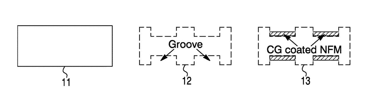
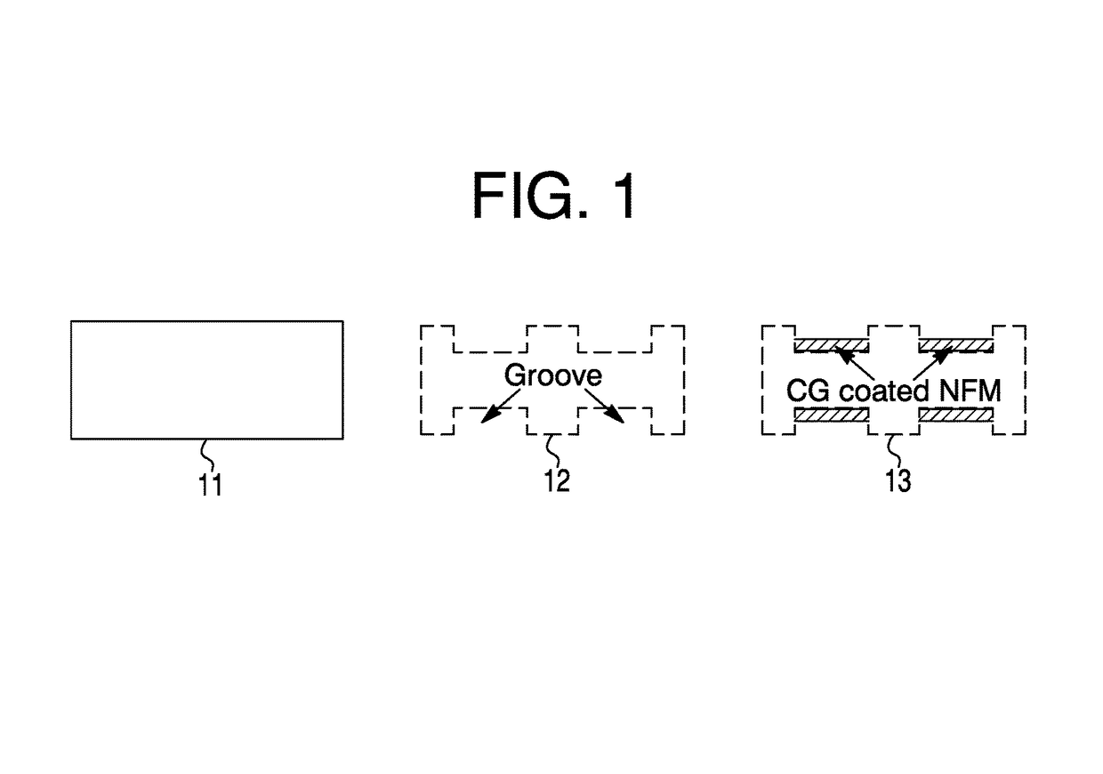
[0040]Referring now to FIG. 1, a non-limiting diagram shows schematic images of a longitudinal cross-section of a Ti rod without grooves 11, with circumferential grooves 12, and with circumferential grooves and nanofiber matrix (NFM) applied 13. The process of the present invention provides a method for controlled fabrication of microgrooves 12 around the circumference of a Ti implant 11. The present invention provides techniques to attach ENF fibers to an implant surface as shown positioned within the groves 13.

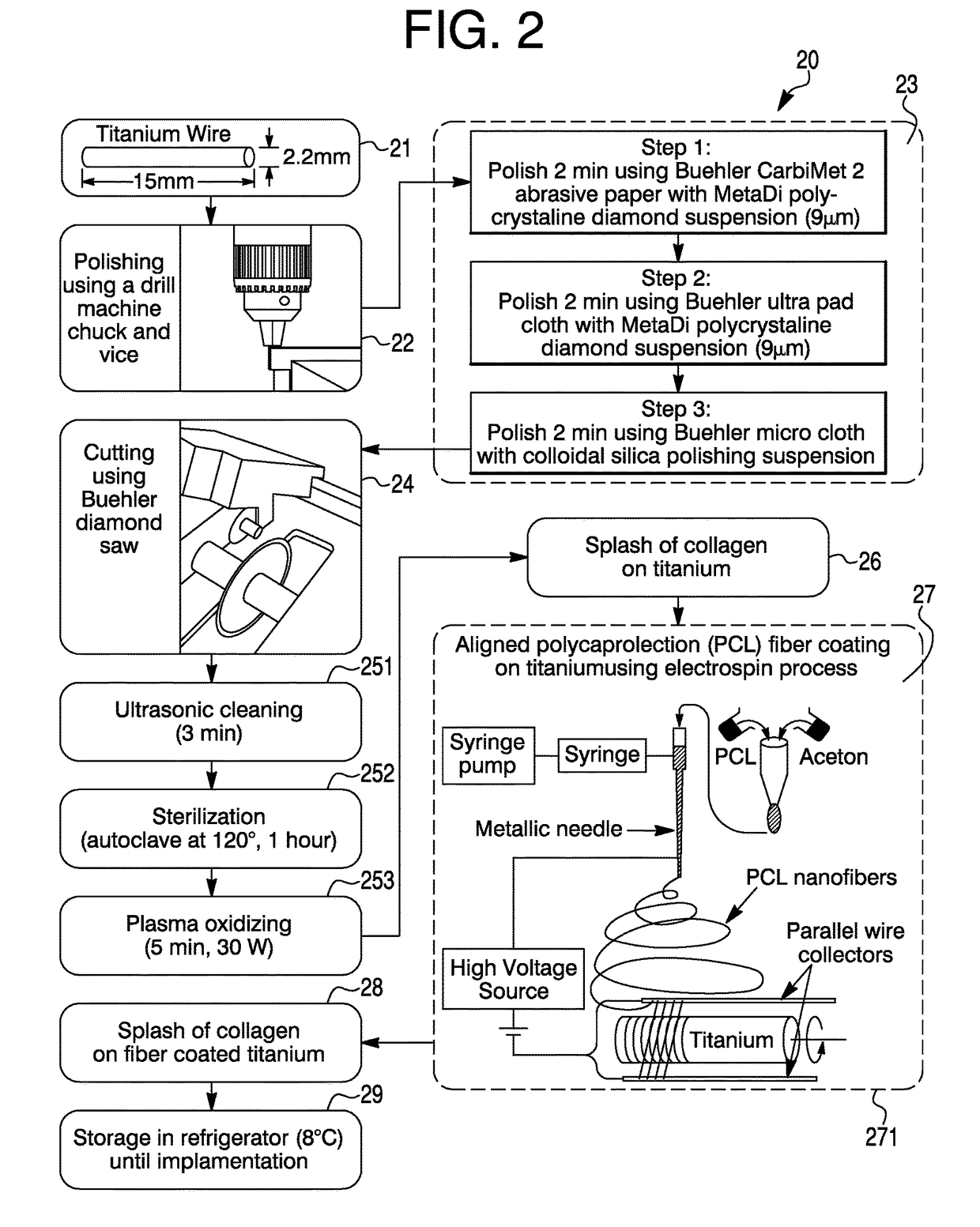
[0041]Referring now to FIG. 2, a non-limiting diagram shows the process of the present invention providing a method 20 for coating a metal implant with electrospun nanofiber, and includes a set of steps (shown in block diagram) by which PCL ENF can be bonded with the metal implant [See FIG. 8, 83]. Briefly, a Ti implant 21 (e.g., 2.2 mm×15 mm wire) may be polished using a drill machine chuck and gripper 22. Other functionally equivalent rotating devices may be used. A Ti imp...


PUM

PropertyMeasurementUnit
diametersaaaaaaaaaa
diametersaaaaaaaaaa
diameteraaaaaaaaaa

Abstract

The present invention implements a set of grooves / ridges created on Ti at the circumferential direction to increase surface area of implant in contact with bone. These grooves / ridges protect nanofiber matrix (NFM) made with Polycaprolactone (PCL) electrospun nanofiber (ENF) and collagen at the groove from physiological loading. Controlled fabrication of a ridge made with titanium nitride (TiN) around the circumference of Ti is provided using a plasma nitride deposition technique. PCL ENF may be deposited along the sub-micrometer grooves using the electrospin setup disclosed. The method provides for fabrication of microgroove on Ti using machining or TiN deposition and filling the microgrooves with the NFM. This method has proven through experimentation to be successful in increasing in vivo mechanical stability and promoting osseointegration on Ti implants. The immobilization of MgO NP and FN with the PCL-CG NFM on microgrooved Ti as provided in the invention optimizes biological performances of Ti.

Description

CROSS REFERENCES TO RELATED APPLICATIONS[0001]This application claims the benefit of U.S. Provisional Patent Application No. 62 / 312,041 filed on Mar. 23, 2016 in the name of Morshed Khandaker and Shahram Riahinezhad, which is expressly incorporated herein by reference in its entirety. This application is a continuation-in-part of U.S. patent application Ser. No. 14 / 734,147 filed Jun. 9, 2015 by the University of Central Oklahoma (Applicant), entitled “Method and apparatus for controlled alignment and deposition of branched electrospun fiber”. This application also claims the benefit of U.S. Provisional Patent Application No. 62 / 038,506 filed on Aug. 18, 2014 in the name of Morshed Khandaker and William Paul Snow.STATEMENT AS TO RIGHTS TO INVENTIONS MADE UNDER FEDERALLY SPONSORED RESEARCH OR DEVELOPMENT[0002]This invention was made with government support under Grant Number 8P20GM103447 awarded by the National Institutes of Health. The government has certain rights in the invention.F...

Claims


Application Information

Patent Timeline
Patent Type & Authority Patents(United States)
IPC IPC(8): A61F2/28D01D11/06A61F2/30D01D5/00
CPCD01D11/06A61F2/28A61F2002/2817D10B2509/00A61F2310/00023D01D5/0007D10B2331/041A61F2002/30677D01D5/0084D01F1/10D01F6/625A61F2/30771A61F2002/3082A61F2002/30838A61F2002/3084A61F2002/30909
Inventor KHANDAKER, MORSHEDRIAHINEZHAD, SHAHRAM
Owner UNIVERSITY OF CENTRAL OKLAHOMA
Why Eureka
Try Eureka