
Polyimide resin

a polyimide resin and polyimide technology, applied in the field of thermoplastic polyimide resins, can solve the problems of low molding process ability, difficult processing, and lack of thermoplasticity, and achieve the effects of high heat resistance, high mold processability and heat resistance, and good balan

Active Publication Date: 2018-01-23
MITSUBISHI GAS CHEM CO INC
View PDF15 Cites 1 Cited by
  • Summary
  • Abstract
  • Description
  • Claims
  • Application Information

AI Technical Summary

Benefits of technology

[0027]The polyimide resin of the present invention has molding processability and heat resistance in a well-balanced manner and has higher solder reflow resistance. The polyimide resin of the present invention has particularly high molding processability, and therefore is preferably used for production of a molded article at least partially having a thin portion, such as a film, a plate or a small component. In addition, a molded article comprising the polyimide resin not only is excellent in heat resistance, but also is less deformed and decreased in strength even if subjected to a solder reflow process, and has excellent solder reflow resistance.

Problems solved by technology

While a polyimide resin has high heat resistance, however, it has the problems of exhibiting no thermoplasticity and having low molding process ability.
This resin is difficult to process by molding due to its very low flowability even at a high temperature, and is also disadvantageous in terms of cost because it requires molding under conditions of a high temperature and a high pressure for a prolonged period of time.
Aurum is, however, limited in terms of an available apparatus because of having a high melting point and requiring a molding temperature of generally 400° C. or more.
This reduces the rigidity of the polyimide resin, and thus also decreases the melting point.
This method, however, might decrease the glass transition temperature along with the decrease of the melting point, and in particular, might reduce the strength at a high temperature.
Another problem of this method is difficult synthesis of a polyimide resin using a raw material diamine composed mainly of an aliphatic diamine.

Method used


Image

  • Polyimide resin
  • Polyimide resin
  • Polyimide resin

Examples


example 1

[Example 1] Production of Polyimide Resin 1

[0234]600 g of 2-(2-methoxyethoxy)ethanol (produced by Nippon Nyukazai Co., Ltd.) and 218.58 g (1.00 mol) of pyromellitic dianhydride (produced by Mitsubishi Gas Chemical Company, Inc.) were introduced in a 2 L separable flask equipped with a Dean-Stark apparatus, a Liebig condenser tube, a thermocouple, and a four-paddle blade. After creation of a nitrogen flow, the mixture was agitated at 150 rpm so as to become a homogeneous suspended solution. On the other hand, 49.42 g (0.347 mol) of 1,3-bis(aminomethyl)cyclohexane (produced by Mitsubishi Gas Chemical Company, Inc.) and 93.16 g (0.645 mol) of 1,8-octamethylenediamine (produced by Kanto Chemical Co., Inc.) were dissolved in 250 g of 2-(2-methoxyethoxy)ethanol with a 500 mL beaker, thereby preparing a mixed diamine solution. This mixed diamine solution was gradually added thereto with a plunger pump. The dropwise addition of the mixed diamine solution was carried out in a nitrogen flow s...

example 2

[Example 2] Production of Polyimide Resin 2

[0238]500 g of 2-(2-methoxyethoxy)ethanol (produced by Nippon Nyukazai Co., Ltd.) and 109.06 g (0.500 mol) of pyromellitic dianhydride (produced by Mitsubishi Gas Chemical Company, Inc.) were introduced in a 2 L separable flask equipped with a Dean-Stark apparatus, a Liebig condenser tube, a thermocouple, and a four-paddle blade. After creation of a nitrogen flow, the mixture was agitated at 150 rpm so as to become a homogeneous suspended solution. On the other hand, 21.18 g (0.149 mol) of 1,3-bis(aminomethyl)cyclohexane (produced by Mitsubishi Gas Chemical Company, Inc.) and 50.12 g (0.347 mol) of 1,8-octamethylenediamine (produced by Kanto Chemical Co., Inc.) were dissolved in 200 g of 2-(2-methoxyethoxy)ethanol with a 500 mL beaker, thereby preparing a mixed diamine solution. This mixed diamine solution was gradually added thereto with a plunger pump. The dropwise addition of the mixed diamine solution was carried out in a nitrogen flow ...

example 3

[Example 3] Production of Polyimide Resin 3

[0240]500 g of 2-(2-methoxyethoxy)ethanol (produced by Nippon Nyukazai Co., Ltd.) and 109.06 g (0.500 mol) of pyromellitic dianhydride (produced by Mitsubishi Gas Chemical Company, Inc.) were introduced in a 2 L separable flask equipped with a Dean-Stark apparatus, a Liebig condenser tube, a thermocouple, and a four-paddle blade. After creation of a nitrogen flow, the mixture was agitated at 150 rpm so as to become a homogeneous suspended solution. On the other hand, 17.65 g (0.124 mol) of 1,3-bis(aminomethyl)cyclohexane (produced by Mitsubishi Gas Chemical Company, Inc.) and 53.70 g (0.372 mol) of 1,8-octamethylenediamine (produced by Kanto Chemical Co., Inc.) were dissolved in 200 g of 2-(2-methoxyethoxy)ethanol with a 500 mL beaker, thereby preparing a mixed diamine solution. This mixed diamine solution was gradually added thereto with a plunger pump. This dropwise addition of the mixed diamine solution was carried out in a nitrogen flow...


PUM

PropertyMeasurementUnit
thicknessaaaaaaaaaa
temperatureaaaaaaaaaa
Tgaaaaaaaaaa

Abstract

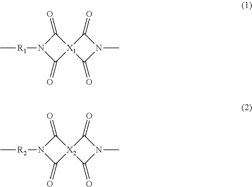
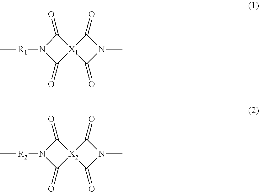
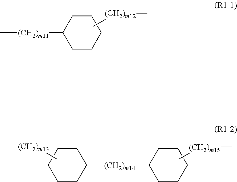
A polyimide resin containing a repeating structural unit represented by the following formula (1) and a repeating structural unit represented by the following formula (2), a content ratio of the repeating structural unit of formula (1) with respect to the total of the repeating structural unit of formula (1) and the repeating structural unit of formula (2) being 20 mol % or more and less than 40 mol %, and the polyimide resin satisfying predetermined conditions:wherein R1 represents a divalent group having from 6 to 22 carbon atoms containing at least one alicyclic hydrocarbon structure; R2 represents a divalent chain aliphatic group having from 5 to 16 carbon atoms; and X1 and X2 each independently represent a tetravalent group having from 6 to 22 carbon atoms containing at least one aromatic ring.

Description

TECHNICAL FIELD[0001]The present invention relates to a thermoplastic polyimide resin.BACKGROUND ART[0002]A polyimide resin is a useful engineering plastic that has high thermal stability, high strength and high solvent resistance due to rigidity, resonance stabilization and firm chemical bond of the molecular chain thereof, and is being applied to a wide range of fields. A polyimide resin having crystallinity is further enhanced in the heat resistance, the strength and the chemical resistance thereof, and thus is expected for applications as alternatives of metals or the like. While a polyimide resin has high heat resistance, however, it has the problems of exhibiting no thermoplasticity and having low molding process ability.[0003]Vespel (registered trademark), a highly heat-resistant resin, is known as a polyimide molding material (PTL 1). This resin is difficult to process by molding due to its very low flowability even at a high temperature, and is also disadvantageous in terms...

Claims


Application Information

Patent Timeline
Patent Type & Authority Patents(United States)
IPC IPC(8): C08G73/10C08J5/18
CPCC08G73/1082C08J5/18C08J2379/08C08G73/1042C08G73/1017C08G73/10C08J5/00
Inventor SATO, YUUKI
Owner MITSUBISHI GAS CHEM CO INC
Learn More