
Conductive composition, and conductive complex

a technology of electrical conductivity and composition, applied in the direction of non-conductive materials with dispersed conductive materials, chemical/physical processes, inorganic chemistry, etc., can solve the problems of low heat resistance, fragmentation of cnts, and low dispersibility of small molecules dispersants, so as to increase the electrical conductivity of composites, suppress composition changes, and maintain stably

Active Publication Date: 2018-02-13
NISSAN CHEM IND LTD
View PDF42 Cites 0 Cited by
  • Summary
  • Abstract
  • Description
  • Claims
  • Application Information

AI Technical Summary

Benefits of technology

This patent describes a conductive composition that includes carbon nanotubes and a dopant precursor. The dopant precursor is a neutral acid generator that helps maintain the stable dispersed state of the carbon nanotubes. The composition has low pH changes and weak interactions with the carbon nanotubes and dispersant, making it easy to maintain the stable dispersed state. The dopant precursor can generate acid upon external stimulus, allowing for control over doping and reducing effects on the base material. The composition can be easily formed into a thin-film with high electrical conductivity, making it useful in various applications. The carbon nanotubes can be obtained by methods such as arc discharge, chemical vapor deposition, or laser ablation. The composition can also include other polymer compounds containing an aromatic ring as the repeating unit. The carbon nanotubes need to be purified and used under suitable conditions to maintain their properties.

Problems solved by technology

Various dispersants, ranging from small molecules to polymers, are being investigated, although small-molecule dispersants generally have a low dispersibility and a poor heat resistance.
Techniques for introducing functional groups onto CNTs themselves by chemical treatment, heat treatment or the like are being attempted, although this leads to new problems such as fragmentation of the CNTs and a decline in the electrical conductivity due to breakup of the conjugated system.
When a conductive polymer is used, the conductivity properties of the resulting composition are improved, but this is accompanied by drawbacks; namely, a decrease in transparency due to light absorption by the dispersant, and the color tone.
Yet, when such dopants are added to a CNT dispersion, the dispersed state of the CNTs sometimes becomes unstable due to changes in the pH of the dispersion or to interactions by the dopant with the CNTs, the dispersant and the dispersion medium.
However, in such cases, in addition to the problem that dopant does not fully penetrate to the interior, further drawbacks include an increase in the costs associated with the process, and the desire for a high chemical stability in the base material used because of a high reactivity of dopants.

Method used


Image

  • Conductive composition, and conductive complex
  • Conductive composition, and conductive complex
  • Conductive composition, and conductive complex

Examples


synthesis example 1

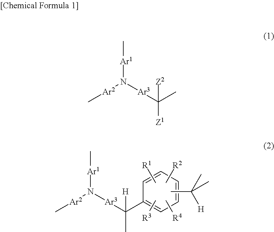
[0159]Synthesis of the Highly Branched Polymer PTPA-PBA

[0160]Under a nitrogen atmosphere, a 200 mL four-neck flask was charged with 5.0 g (20 mmol) of triphenylamine (Tokyo Chemical Industry), 7.4 g (41 mmol, 2.0 eq. relative to the triphenylamine) of 4-phenylbenzaldehyde (Mitsubishi Gas Chemical), 1.2 g (6.1 mmol, 0.3 eq. relative to the triphenylamine)) of PTSA and 10 g of 1,4-dioxane. The temperature of the mixture was raised to 100° C. under stirring, bringing about dissolution and commencing polymerization. The reaction was carried out for 45 minutes, after which the reaction mixture was allowed to cool to 60° C. The reaction mixture was then diluted with 100 g of THF and subsequently poured into a mixed solution of 250 g of acetone, 250 g of methanol and 20 g of 28 wt % ammonia water, and thereby re-precipitated. The precipitate was collected by filtration, and the resulting solid was re-dissolved in 100 g of THF. This solution was then poured into a mixed solution of 250 g of...

example 1

[0163]Production of Photoacid Generator-Containing Conductive Composition and Conductive Composite (1)

Production of Conductive Composition:

[0164]First, 50 mg of the PTPA-PBA synthesized in Synthesis Example 1 as the dispersant was dissolved in 50 g of NMP, following which 50 mg of CNT-1 as the SWCNTs was added to the solution. The resulting mixture was subjected to 10 minutes of ultrasonic treatment at room temperature (about 25° C.) using a probe-type sonicator. The treated mixture was left at rest overnight at room temperature (about 25° C.), then centrifuged for 1 hour at 10,000 g and room temperature (about 25° C.). The black supernatant that formed was then collected as a SWCNT-containing dispersion.

[0165]To 8 g of this SWCNT-containing dispersion was added 8 mg of the photoacid generator CPI as a dopant precursor and 2 g of CHN as a wetting agent, thereby forming a conductive composition. This composition was left at rest overnight at room temperature (about 25° C.), following...

example 2

[0169]Production of Photoacid Generator-Containing Conductive Composition and Conductive Composite (2)

[0170]Aside from changing the dopant to 8 mg of the photoacid generator PI, preparation of a conductive composition, production of a conductive composite and evaluation were carried out in the same way as in Example 1. The results are shown in Table 1.

[0171]The UV-visible-near IR absorption spectrum for the resulting conductive composition coating fluid was measured in the same way as in Example 1, from which the SWCNTs were confirmed to be dispersed in an individually dispersed state.


PUM

PropertyMeasurementUnit
temperatureaaaaaaaaaa
timeaaaaaaaaaa
timeaaaaaaaaaa

Abstract

A conductive composition containing carbon nanotubes, a carbon nanotube dispersant, and a dopant precursor, wherein the dispersant is a non-conjugated polymer compound having an aromatic ring as the repeating unit, and the dopant precursor is an acid-generating agent which generates cation by being subjected to light and / or heat. The aforementioned conductive composition is capable of stably dispersing carbon nanotubes and of efficiently doping same without damaging the conductive properties of the carbon nanotubes.

Description

TECHNICAL FIELD[0001]The present invention relates to an electrically conductive composition and an electrically conductive composite.BACKGROUND ART[0002]Carbon nanotubes (abbreviated below as “CNTs”) are structures that can be counted on to have a high electrical conductivity, and are being studied for potential use in a wide range of fields as a key nanotechnology material.[0003]In the actual use of such CNTs, to achieve a high conductivity in a smaller amount, the CNTs must be uniformly dispersed within a polymer or the like that serves as a matrix material.[0004]Dispersion methods can be broadly divided into methods that involve modifying the carbon nanotubes themselves so that they easily disperse in the matrix material, and methods that involve the use of a dispersant such as a surfactant or a polymer.[0005]Of these, methods involving the use of a dispersant are commonly employed because the carbon nanotubes can be uniformly and highly dispersed while retaining their electrica...

Claims


Application Information

Patent Timeline
Patent Type & Authority Patents(United States)
IPC IPC(8): H01B1/04B82Y40/00C09D201/00C08L101/00C08G12/08H01B1/24C09D179/08C08G73/02C01B32/05C01B32/174B82Y30/00C08K3/04C09D161/22C09K23/16C09K23/52
CPCH01B1/24B82Y40/00C01B32/05C01B32/174C08G12/08C08G73/026C08K3/04C08L101/005C09D161/22C09D179/08C09D201/005B82Y30/00C08L65/00C08K5/42Y10S977/742C08G2261/3162C08G2261/792C08K3/041
Inventor HATANAKA, TATSUYAHIDA, MASAHIRO
Owner NISSAN CHEM IND LTD
Learn More