High performance, thin metal lined, composite overwrapped pressure vessel

a composite overwrapped and pressure vessel technology, applied in the field of composite overwrapped pressure vessels, can solve the problems of not being able to fabricate a liner with the proper characteristics, not being able to withstand the weight of non-composite overwrapped metal tanks, and several failures, and achieve high ductility and high f.sup.ty/e

Inactive Publication Date: 2004-02-24
LOCKHEED MARTIN CORP
View PDF31 Cites 24 Cited by
  • Summary
  • Abstract
  • Description
  • Claims
  • Application Information

AI Technical Summary

Benefits of technology

It is also an object of the present invention to produce a COPV with a

Problems solved by technology

Each key operation had to be optimized for use in an overwrapped pressure vessel application, because the strain levels in the metal are well above yield, which non-composite overwrapped metal tanks are not designed to withstand.
During the course of the development of the technology, several failures were encountered due to manufacturing techniques that were not capable of fabricating a liner with the proper characteristics.
Initial attempts to use industry-standard spun-dome processing (developed for all metal tanks) proved inadequate for this application.
The early cylinders were fabricated using a Tungsten Inert Gas (TIG) welding technique, which even after numerous refinements was not capable of consistently performing in this application.
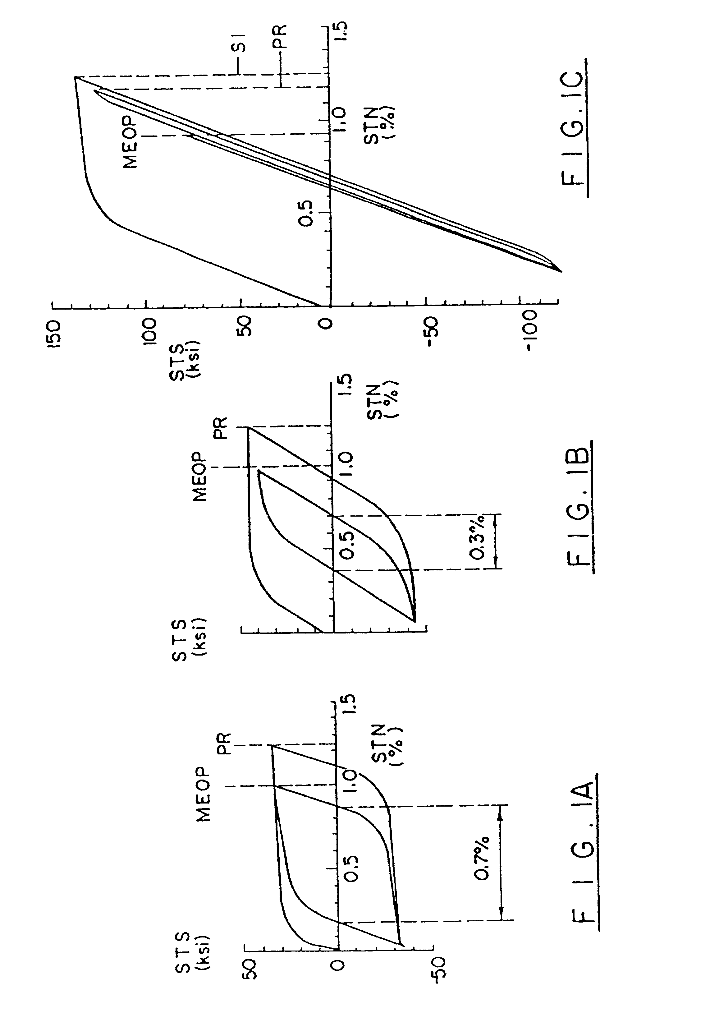
This is critical because even the best high-temperature vacuum stress-relieve operations produce a very thin layer of oxygen contamination (FIG. 6) which has been shown to crack under high strains (early tanks which were vacuum stress relieved exhibited cracks, some of which penetrated through the liner).
Initially, three liner systems were considered, aluminum--the current state of the art, electroplated copper--a developmental technology with limited success in preliminary development with the potential for very low weight, and titanium alloy.
The titanium was selected over electroplated copper because of the high d

Method used


Image

  • High performance, thin metal lined, composite overwrapped pressure vessel
  • High performance, thin metal lined, composite overwrapped pressure vessel
  • High performance, thin metal lined, composite overwrapped pressure vessel

Examples


Embodiment Construction

The following table lists the part numbers and part descriptions as used herein and drawings attached hereto. The preferred materials, if any, follow in parentheses.

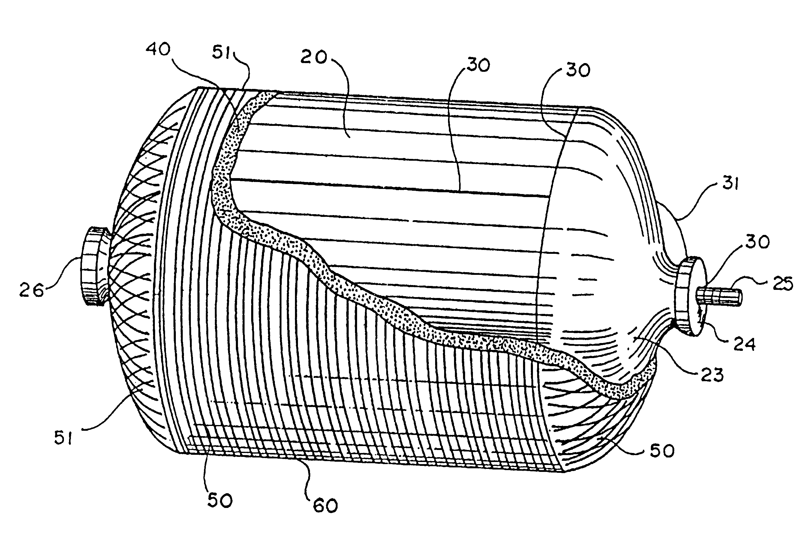
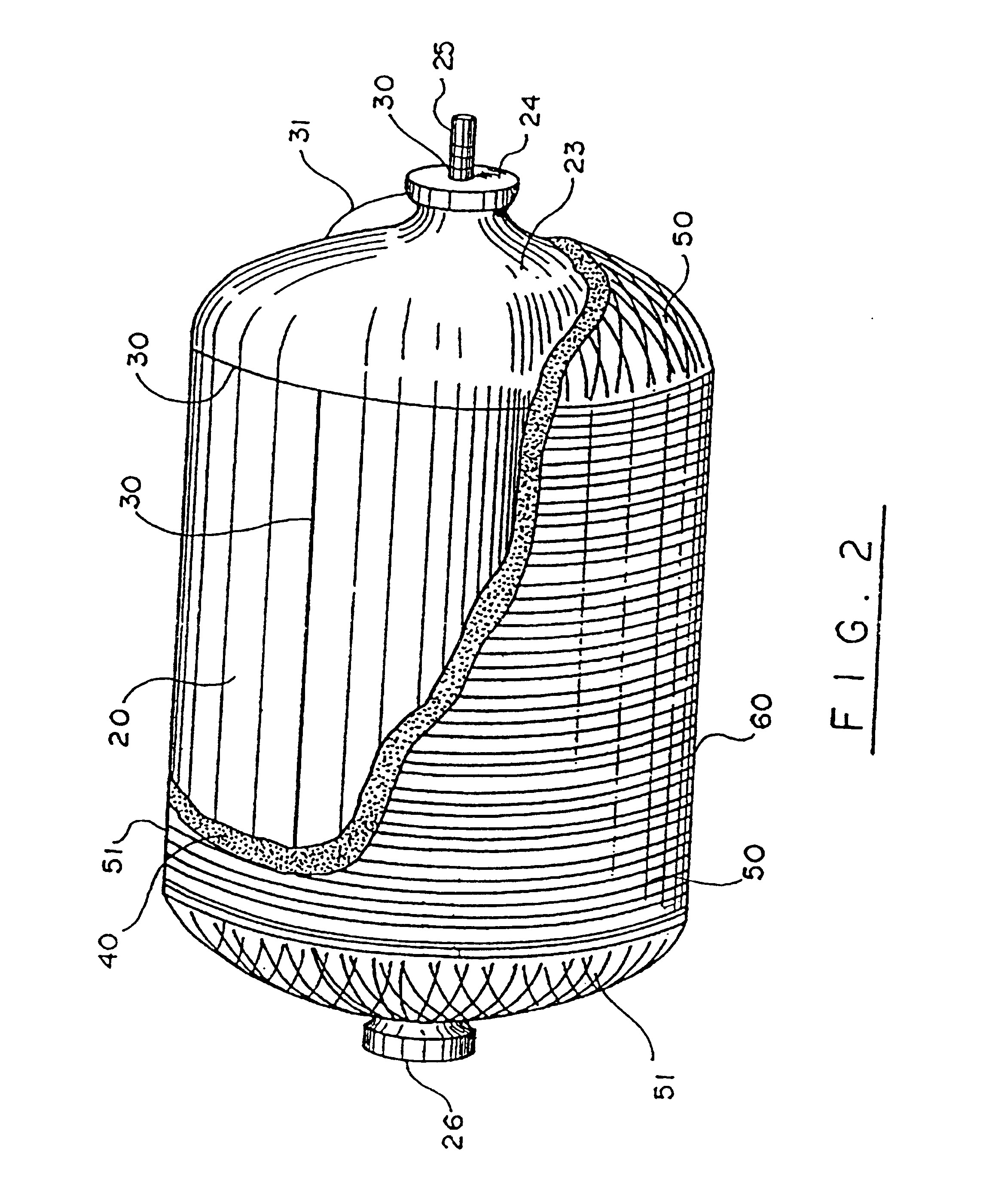
PARTS LIST Part Number Description 10 COPV of the first embodiment of the present invention 20 liner (titanium-alloy) 20M maximum thickness of domes 21, 23 21 spun-formed dome (Ti-6Al-4V) 22 liner cylinder (Ti-6Al-4V) 23 spun-formed dome (Ti-6Al-4V) 24 machined boss (Ti-6Al-4V) 25 machined tube (Ti-6Al-4V) 26 machined boss (Ti-6Al-4V) 27 fitting used to test tank 28 holes in boss 24 29 holes in boss 26 30 EB welds 31 preferred region for boss / dome weld 40 adhesive (AF-191) 50 filament-wound graphite-epoxy overwrap (T-1000 / EPON 862- Curing Agent W) 51 graphite windings of filament-wound graphite-epoxy overwrap 50 60 epoxy coating (EPON 862-Curing Agent W) 120 liner (titanium-alloy) 120M maximum thickness of domes 121, 123 121 spun-formed dome (Ti-6Al-4V) 123 spun-formed dome (Ti-6Al-4V) 124 machined boss (Ti-6Al-4V) 126 m...


PUM

PropertyMeasurementUnit
Lengthaaaaaaaaaa
Fractionaaaaaaaaaa
Fractionaaaaaaaaaa

Abstract

An innovative technology for composite overwrapped pressure vessels (COPVs) has been developed which significantly increases cost effectiveness, increases reliability, and reduces weight over state-of-the-art COPVs. This technology combines an innovative thin liner made of a metal having a high modulus of elasticity and a high ductility, a high-performance composite overwrap and a high-performance film adhesive at the overwrap/liner interface. The metal liner can be fabricated from readily available titanium alloy sheet and plate using a combination of spin forming and machining to fabricate components and electron-beam welding for tank assembly. The composite overwrap is filament-wound onto an adhesive-covered titanium liner and the overwrap and adhesive are co-cured in an oven to yield an integrated tank structure.

Description

BACKGROUND OF THE INVENTION1. Field of the InventionThe present invention relates to composite overwrapped pressure vessels (COPV's) and their method of manufacture. More specifically, the present invention relates to high-performance COPV's including liners made of metals which exhibit high moduli of elasticity and high ductility, such as titanium alloys.2. General BackgroundThe basic technology for composite overwrapped pressure vessels with metal liners dates back to the late 60's and early 70's.High-performance fibers offer very high strength-to-weight ratios and are ideal for making lightweight pressure vessels. However, composite laminates fabricated with these fibers have relatively high permeability and cannot contain high pressure liquids or gasses or low pressure gasses for extended periods of time. Therefore, composite pressure vessels must have a liner to prevent leakage. The tank efficiency, as measured by its pressure multiplied by its volume divided by its weight (PV / ...

Claims


Application Information

Patent Timeline
IPC IPC(8): B23K15/00B21D51/24B21D51/16F17C1/06F17C1/00B29C53/00B29C53/58
CPCB21D51/24B29C70/088F17C1/06B23K15/0046Y10T29/49906B29C53/58B29K2105/0097B29K2705/00B29L2031/7156F17C2201/0109F17C2201/056F17C2201/058F17C2203/0604F17C2203/0607F17C2203/0621F17C2203/0636F17C2203/0643F17C2203/0648F17C2203/0665F17C2203/0668F17C2203/0673F17C2205/0305F17C2205/0397F17C2209/2154F17C2209/2163F17C2209/221F17C2209/227F17C2209/232F17C2209/234F17C2221/011F17C2221/08F17C2223/0123F17C2223/036F17C2260/011F17C2260/012F17C2260/013F17C2260/036F17C2260/042F17C2260/05F17C2270/0194F17C2270/0197
Inventor SEAL, ELLIS C.ELFER, NORMAN C.BRANDT, TORBENEDMAN, ROBERT O.
Owner LOCKHEED MARTIN CORP
Why Eureka
Try Eureka