System and method for dynamic clock generation

a dynamic clock and clock technology, applied in the field of portable electronic devices, can solve the problems of essentially waste of power used to operate at the higher-frequency clock, a significant amount of power required by the clock asic to provide this functionality, and achieve the effect of saving power and reducing power consumption

Inactive Publication Date: 2007-12-25
HANGER SOLUTIONS LLC +1
View PDF3 Cites 8 Cited by
  • Summary
  • Abstract
  • Description
  • Claims
  • Application Information

AI Technical Summary

Benefits of technology

[0017]Thus, the clock frequency for the resource is automatically determined by the total bandwidth utilized of the controllers requesting access to the resource. Accordingly, the clock frequency is preferably chosen so that the bandwidth of the resource closely matches the needed bandwidth. As a result, little power is wasted due to operating the resource at a higher clock frequency than is necessary. A preferred embodiment of the present invention further conserves power by shutting off the memory clock when no controllers are requesting access to the memory controller.

Problems solved by technology

However, the CMOS ASIC requires a significant amount of power to provide this functionality.
Since there is a general desire to operate the device at its highest speed, the clocks are usually run at a high frequency and therefore dissipate power at a high rate.
Moreover, if a device is operated with a clock frequency higher than is necessary, the power utilized to operate at the higher-frequency clock is essentially wasted.
Assuming that there are on concurrent memory requests from other devices, the power needed to drive the system memory at a higher frequency than is needed to support the IR transceiver is essentially wasted.
In addition, the “Clock I / O” pin to the external memory also toggles continuously, thereby consuming power on the clock driver I / O pad and the clock receiver I / O pads.

Method used


Image

  • System and method for dynamic clock generation
  • System and method for dynamic clock generation
  • System and method for dynamic clock generation

Examples


Embodiment Construction

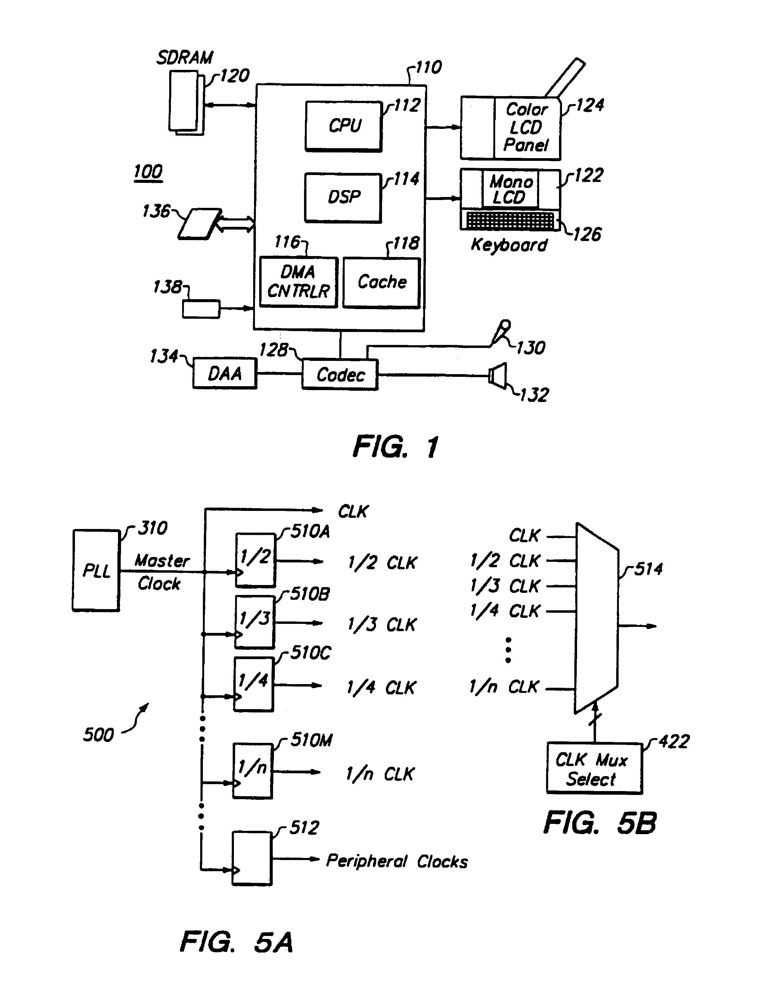
[0026]FIG. 1 is a high-level diagram illustrating the components of a typical portable electronic device 100 according to an embodiment of the present invention. As used herein, the phrase “portable electronic device” refers to the class of devices including smart telephones, screen telephones, and other Internet-ready appliances. The phrase also includes devices such as digital cameras, portable music players, and hand-held computer systems. Of course, the present invention has broad applicability and can be used with any electronic device where power conservation is desired, regardless of whether the device is portable.

[0027]FIG. 1 illustrates an application specific integrated circuit (ASIC) 110, preferably manufactured using a complementary metal oxide semiconductor (CMOS) process, and having a central processing unit (CPU) 112, a digital signal processor (DSP) 114, a direct memory access (DMA) controller 116, and a memory cache 118. Although a preferred embodiment of the presen...


PUM


Abstract

An application specific integrated circuit (ASIC) has a clock controller that dynamically selects an appropriate clock frequency for a resource. The ASIC includes a central processing unit (CPU), on-chip memory, a memory controller controlling external memory devices, a system bus, and various peripheral controllers. Devices that can be accessed by other devices, such as the on-chip memory, the memory controller, and the system bus are “resources.” The devices that access the resources are “controllers.” The ASIC generates a master clock and the clock controller derives clocks for driving the resources and controllers from the master clock. A multiplexer (MUX) in the clock controller selects the clock that is passed to a resource. Each controller has a request line to the clock controller for signaling when the controller is accessing a resource. The clock controller has a programmable register for each controller holding a value representing the bandwidth utilization of the controller and an adder and a frequency table. The adder sums the contents of the bandwidth registers of the controllers that are accessing a resource. The sum is an index to an entry in a frequency table. The value held in the frequency table is applied to the selection inputs of the MUX to select the clock for the resource. If no controllers are requesting access to the memory controller, the clock controller shuts down the memory clock. Accordingly, the clock frequency of the resource is determined by the bandwidth utilization of the controllers requesting access to the resource.

Description

BACKGROUND[0001]1. Field of the Invention[0002]This invention pertains in general to portable electronic devices and in particular to reducing power consumption of such devices by controlling the clock frequencies in the devices.[0003]2. Background of the Invention[0004]The need for portable electronic devices, also referred to as “electronic appliances” is growing rapidly. Numerous small devices, such as the PALM PILOT organizer from 3COM, INC. and MICROSOFT WINDOWS CE-based palm computers have become ubiquitous in society. As the sizes of the devices decrease and the processing powers increase, these devices will become even more prevalent. For example, solid-state music players, smart phones, screen phones, digital cameras, and other Internet-ready electronic appliances will soon become mainstream.[0005]By nature, a portable electronic device should be as small and light as possible. Accordingly, there is a desire to reduce the amount of circuitry within the device by combining f...

Claims


Application Information

Patent Timeline
Patent Type & Authority Patents(United States)
IPC IPC(8): G06F1/32
CPCG06F1/3203G06F1/3237G06F1/324G06F1/3275Y02B60/1228Y02B60/1217Y02B60/1221Y02B60/1225Y02D10/00
Inventor CHEUNG, EDMUNDSPONRING, OTTO
Owner HANGER SOLUTIONS LLC
Why Eureka
Try Eureka