

Aluminum oxide coated tool
a technology of aluminum oxide and cutting tools, applied in the direction of instruments, natural mineral layered products, other chemical processes, etc., can solve the problems of diffusion type crater wear on the rake face of the tool, crater wear on the rake face, etc., and achieve the effect of high resistance to crater wear and flank wear
- Summary
- Abstract
- Description
- Claims
- Application Information
AI Technical Summary
Benefits of technology
Problems solved by technology
Method used
Image

Examples
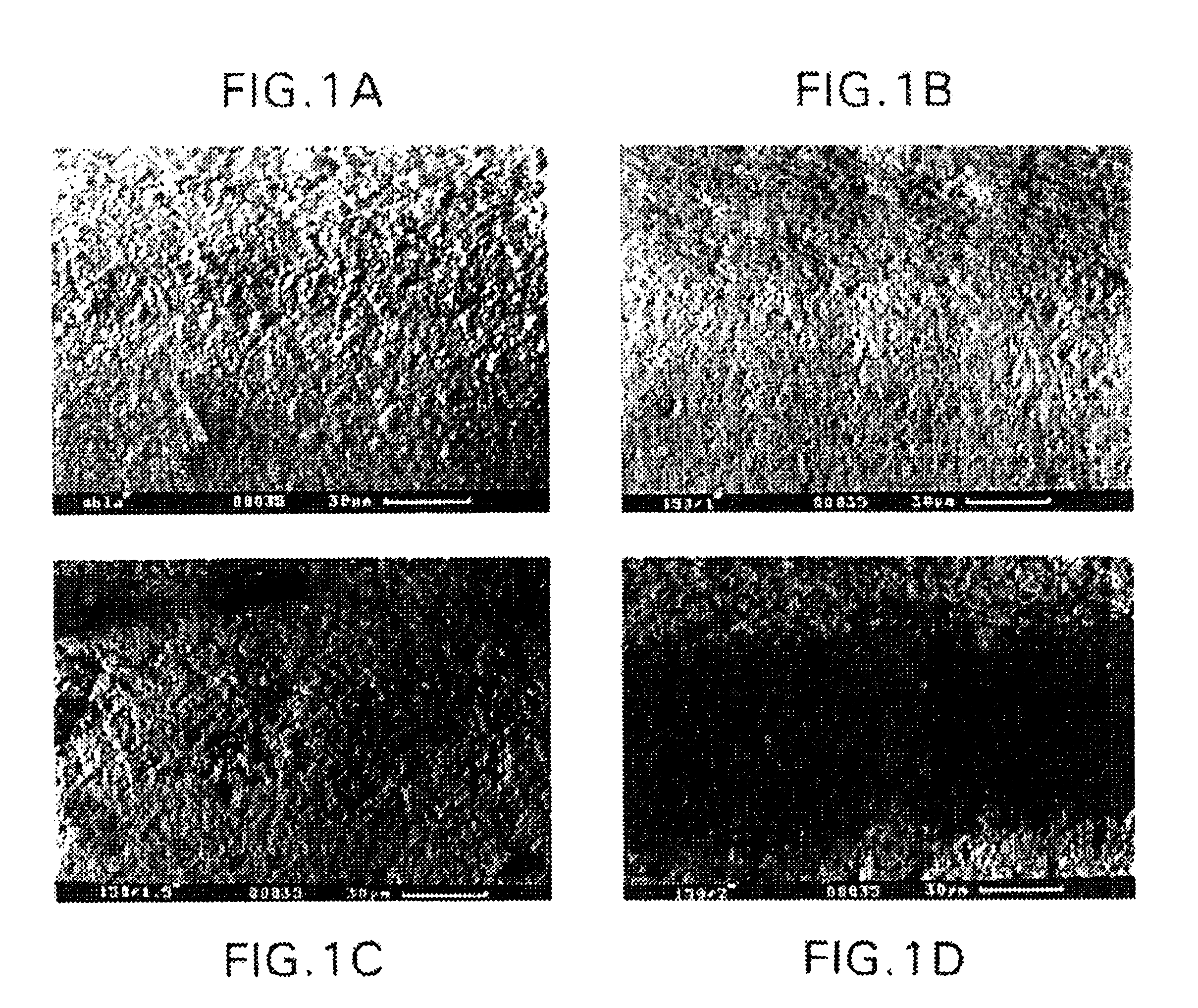
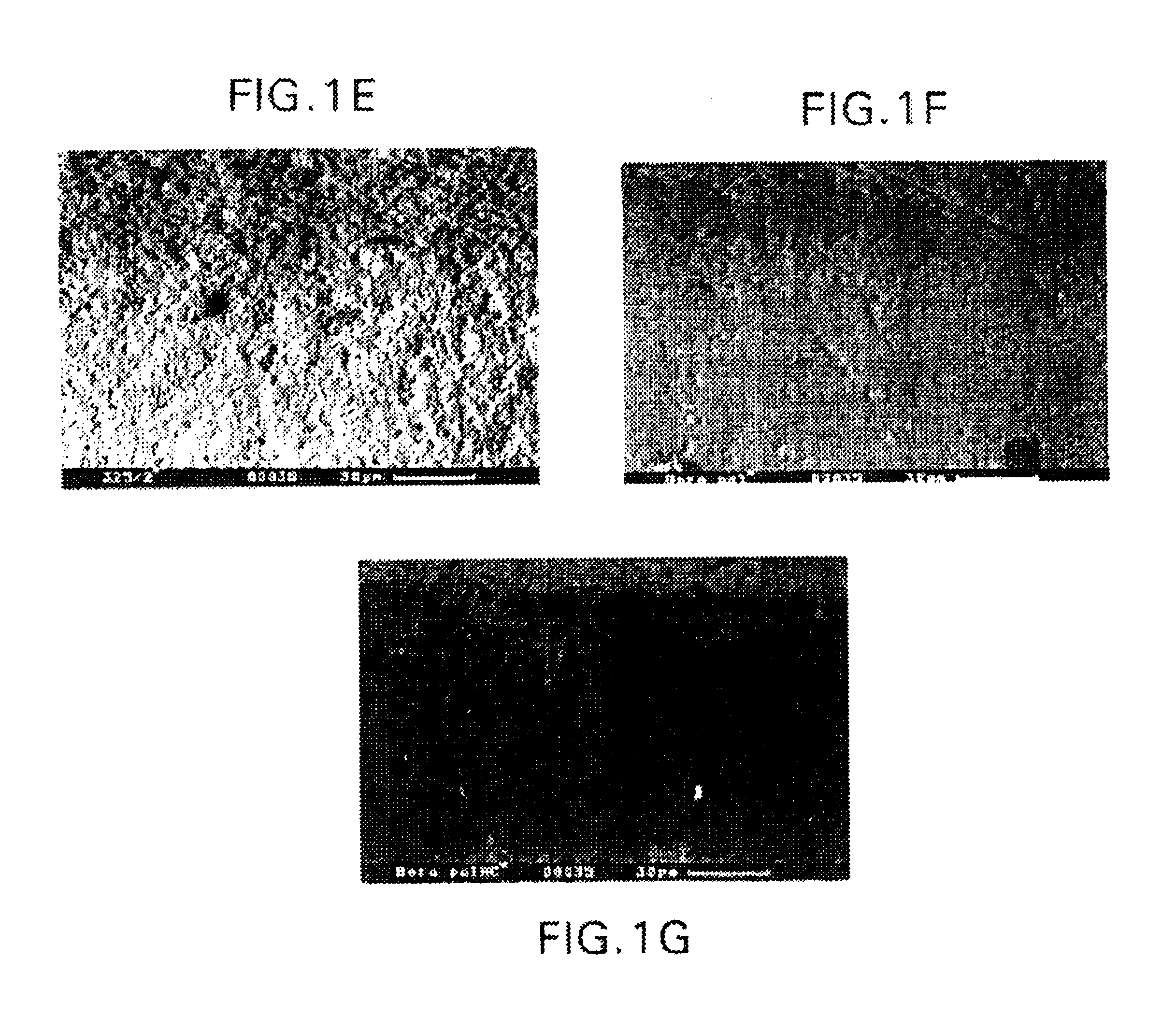
example 1
[0041]Cemented carbide cutting inserts CNMG 120408-QM with the composition 5.5% Co, 8.6% cubic carbides (TiC-TaC-NbC) and balance WC were coated with CVD-technique according to the following sequence: 0.7 μm TiC, 0.5 μm Ti(CO), 8.0 μm Ti(CN), 3.0 μm Al2O3 and 2.8 μm TiN.
[0042]The Al2O3-layer was deposited with a method that gives a fine-grained α-Al2O3 layer according to U.S. Ser. No. 08 / 159,217 (our reference: 024000-993). The TiN-layer was deposited at 400 mbar and the other layers according to prior art techniques.
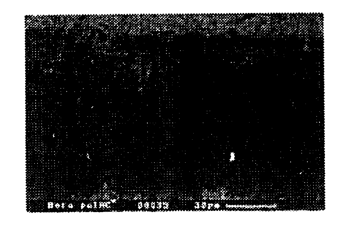
[0043]The coated inserts were post treated with different methods according to below:
[0044]Variant 1A: No post treatment.
[0045]Variant 1B: Wet blasting with 150 mesh Al2O3-grits at 1.0 bar.
[0046]Variant 1C: Wet blasting with 150 mesh Al2O3-grits at 1.5 bar.
[0047]Variant 1D: Wet blasting with 150 mesh Al2O3-grits at 2.0 bar.
[0048]Variant 1E: Wet blasting with 325 mesh Al2O3-grits at 2.0 bar.
[0049]Variant 1F: Brushing with a cylindrical nylon brush containing SiC.
[0050]Va...
example 2
[0059]Cemented carbide cutting inserts CNMG 120408-QM with the composition 5.5% Co, 8.6% cubic carbides (TiC-TaC-NbC) and balance WC were coated with CVD-technique according to the following sequence: 0.6 μm TiC, 0.4 μm Ti(CO), 8.1 μm Ti(CN), 8.1 μm on Al2O3 and 0.9 μm TiN.
[0060]The Al2O3-layer was deposited with a method that gives a fine-grained α-Al2O3 layer according to U.S. Ser. No. 08 / 159,217 (our reference: 024000-993). The TiN-layer was deposited at 400 mbar and the other layers according to prior art techniques.
[0061]The coated inserts were post treated with different methods according to below:
[0062]Variant 2A: No post treatment.
[0063]Variant 2B: Wet blasting with 150 mesh Al2O3-grits resulting in a smoother surface. Here the top TiN-layer was removed along the edge-line as well as on the whole rake face exposing the black Al2O3-layer.
[0064]Variant 2C: Brushing with a cylindrical SiC-containing nylon brush. This treatment resulted in a smooth surface with only the top TiN-...
example 3
[0065]Cemented carbide cutting inserts CNMG 120408-QM with the composition 5.5% Co, 8.6% cubic carbides (TiC-TaC-NbC) and balance WC were coated with CVD-technique according to the following sequence: 1.0 μm TiC, 0.4 μm Ti(CO), 7.9 μm Ti(CN) and 5.5 μm Al2O3.
[0066]The Al2O3-layer was deposited with a method that gives a fine-grained α-Al2O3 layer according to U.S. Ser. No. 08 / 159,217 (our reference: 024000-993).
[0067]The inserts were treated by wet blasting with 150 mesh Al2O3-grits (Variant 3).
PUM
| Property | Measurement | Unit |
|---|---|---|
| Fraction | aaaaa | aaaaa |
| Fraction | aaaaa | aaaaa |
| Fraction | aaaaa | aaaaa |
Abstract
Description
Claims
Application Information