Prefabricated method for thin film microcrack and special apparatus for the same

A thin-film material and micro-crack technology, used in microstructure devices, manufacturing microstructure devices, measuring devices, etc., can solve the problems of difficult to measure crack length, difficult to control crack length, dynamic instability, etc., and achieve regular crack shape and stress. Field simplicity and improved accuracy

Inactive Publication Date: 2008-07-16
INST OF METAL RESEARCH - CHINESE ACAD OF SCI
View PDF6 Cites 0 Cited by
  • Summary
  • Abstract
  • Description
  • Claims
  • Application Information

AI Technical Summary

Problems solved by technology

Due to the limitation of the size of MEMS materials and the particularity of preparation, traditional mechanical property testing techniques and equipment have encountered great difficulties and challenges in the testing of MEMS materials. In recent years, scholars have carried out extensive and in-depth explorations in this area. Various methods such as nanoindentation method, scratch method and uniaxial stretching method have been proposed, but these methods are quite different, and they are especially unreliable in terms of film crack sensitivity and toughness testing
In the study of the mechanical properties of multilayer films, because the multilayer film structure can improve the toughness of the material, the toughness enhancement mechanism is mainly crack tip passivation, crack branching, layer pull-out and interface cracking along the interface, etc. It is very important to conduct related research on prefabricated cracks, but there is still a lack of effective means and methods
At present, the methods of prefabricating microcracks in thin films are mainly laser processing, scratching method, thermal vibration method, fatigue and other methods. However, the prefabricated crack tip of the above methods is a passivation crack, the tip is not clear, and it is difficult to measure the crack length. At the same time, it is difficult to control the crack length , or dynamic instability after the crack is generated, these all give the crack growth resistance under the later plane stress condition, that is, the fracture toughness K c The measurement of

Method used


Image

  • Prefabricated method for thin film microcrack and special apparatus for the same
  • Prefabricated method for thin film microcrack and special apparatus for the same
  • Prefabricated method for thin film microcrack and special apparatus for the same

Examples


Embodiment Construction

[0029] The present invention will be further described below in conjunction with the embodiments and the accompanying drawings.

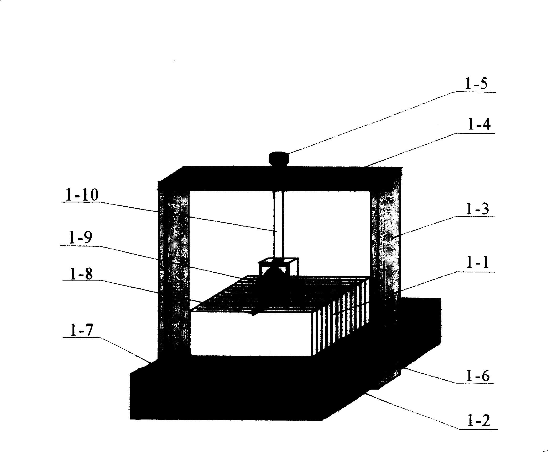
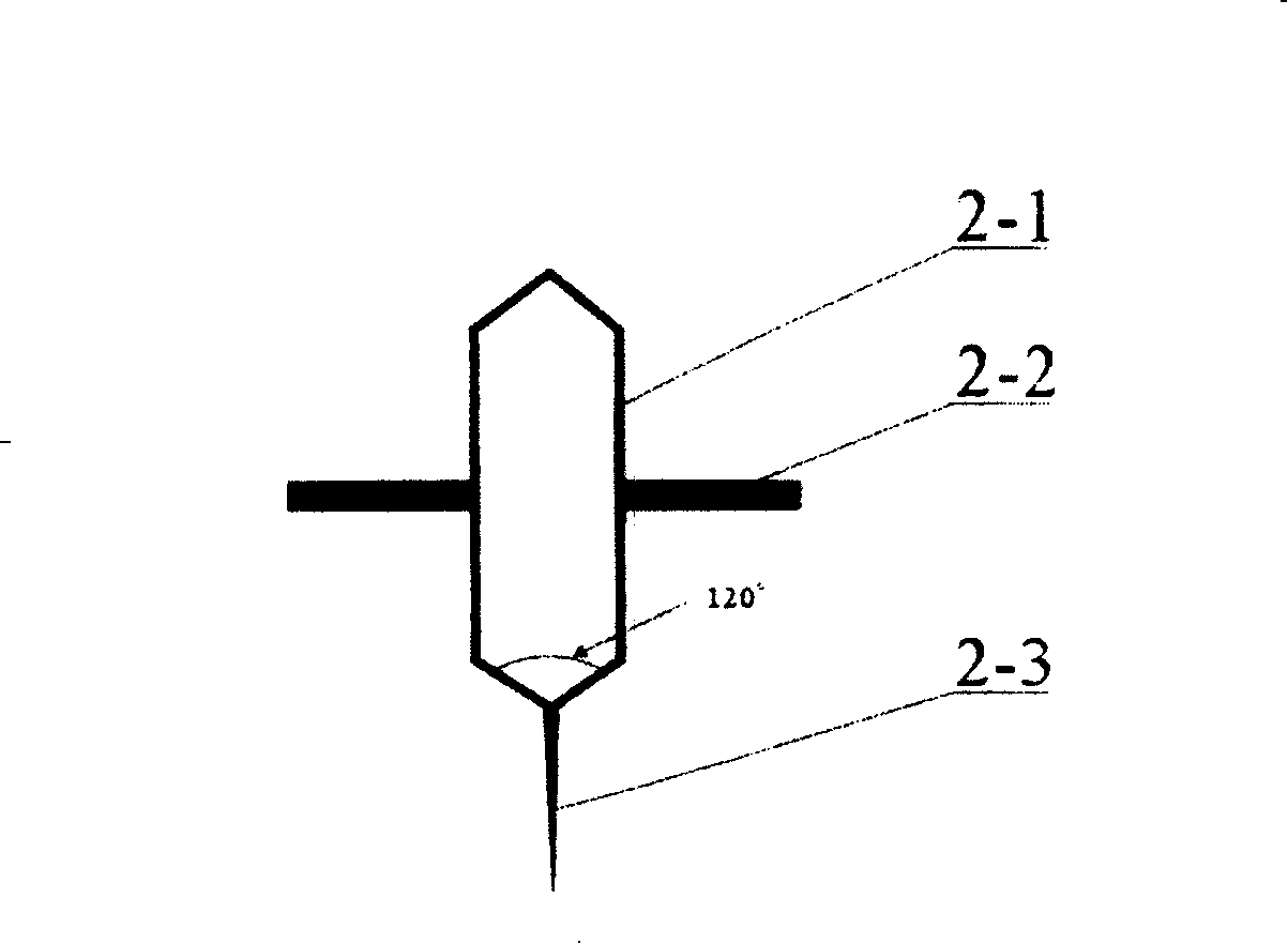
[0030] Such as Figure 1-2 As shown, the microcrack prefabrication device of film material of the present invention is mainly by stage 1-2, dynamometer 1-7, pinch wheel fixed beam (frame) 1-4, load adjustment knob 1-5 and pinch wheel 1-4. 9 components, a force gauge 1-7 for measuring the load pressure is installed on the stage 1-2, and the fixing bolts 1-6 on both sides of the stage 1-2 connect the vertically parallel fixed arms 1-3 Fixed, the top of two parallel fixed roller fixing arms 1-3 is provided with a roller fixing beam 1-4, and the center shaft hole of the roller 1-9 is equipped with a roller fixing pin 2-1, and the roller 1-9 passes through the roller. The wheel fixing pin 2-1 links to each other with the pressure roller support rod 1-10, the pressure roller support rod 1-10 passes through the pressure roller fixed beam 1-4, and is threa...


PUM

PropertyMeasurementUnit
depthaaaaaaaaaa
thicknessaaaaaaaaaa
diameteraaaaaaaaaa

Abstract

The invention discloses a film material micro-cracking preparing method and specific device, which comprises the following steps: fixing film material on the polishing surface of silicon single-wafer, cutting the silicon single-wafer with film material into piece sample, adhering multiple piece samples into block sample with the direction of piece samples consistent, setting film material between two silicon single-wafers, falling the pressurized wheel on one side of micro-crack, making the surface with micro-crack in the whole sliding course to generate micro-crack under the trace. The device is composed of objective table, force gauge, pressurized wheel fixing beam, load adjusting button and pressurized wheel.

Description

technical field [0001] The invention relates to a method for prefabricating microcracks by adhering thin film materials on a single crystal silicon substrate, specifically a method for prefabricating microcracks of thin film materials under load control by using a WC (tungsten carbide) pressure wheel and a special device thereof. Background technique [0002] In recent years, thin-film materials have attracted great attention due to their unique microstructure, physical and chemical properties. With the development of thin-film materials themselves towards functionalization, complexity and low Electromechanical Systems (MEMS) field. With the development and deepening of MEMS research, the basic material properties such as characterizing and testing the mechanical properties of materials have become the key factors to improve the life and reliability of MEMS devices. Due to the limitation of the size of MEMS materials and the particularity of preparation, traditional mechani...

Claims


Application Information

Patent Timeline
Patent Type & Authority Patents(China)
IPC IPC(8): B81C1/00G01L1/00
Inventor 谭军张磊万晔温井龙姚戈
Owner INST OF METAL RESEARCH - CHINESE ACAD OF SCI
Why Eureka
Try Eureka