Device for measuring spectrum image

A technology of image measurement and spectrum, which is applied in the direction of measuring device, color/spectral characteristic measurement, optical radiation measurement, etc., can solve the problems of reducing spectral resolution, misalignment, unsatisfactory, etc., and achieve narrowing of spectral resolution and space The effect of resolution value, reducing the position difference of imaging points, and reducing the degree of diffusion

Active Publication Date: 2009-01-14
IND TECH RES INST
View PDF4 Cites 0 Cited by
  • Summary
  • Abstract
  • Description
  • Claims
  • Application Information

AI Technical Summary

Problems solved by technology

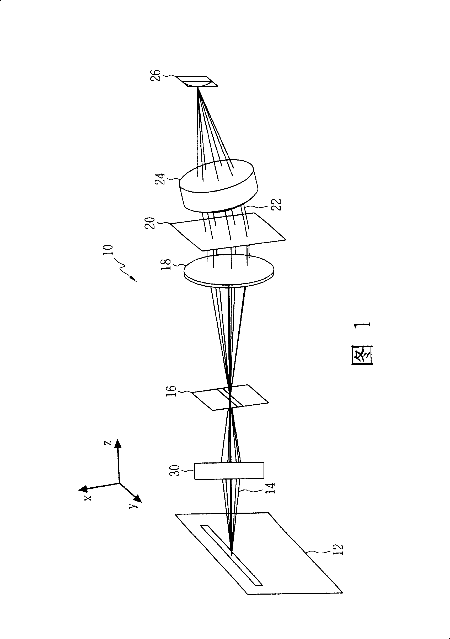
However, since the off-axis light beam of the sample 12 is incident on the optical slit 16 through the imaging mirror 50, the principal ray (principle ray) forms an included angle θ with the optical axis 58 1 (that is, not parallel to the optical axis 58), causing the off-axis light beam to still have a large incollimation after passing through the spherical mirror 54, which cannot meet the requirement of collimated light incident on the grating 56, thus reducing the charge The spectral resolution presented on the coupled sensor 26
In addition, this misalignment also causes additional aberrations, which further reduces the spatial resolution presented on the charge-coupled sensor 26
Therefore, the channel that can be used for measurement is limited by the spectral / spatial resolution and cannot be improved
It can be seen that this design can only be applied to comparisons with low resolution requirements, and cannot produce spectral images with real high spatial / spectral resolution

Method used


Image

  • Device for measuring spectrum image
  • Device for measuring spectrum image
  • Device for measuring spectrum image

Examples


Embodiment Construction

[0021] FIG. 4 illustrates the spectral image measurement device 100 according to the first embodiment of the present invention. The spectral image measurement device 100 includes an image space telecentric mirror 110 for collecting light energy 104 from a sample 102, an optical slit 130 arranged behind the image space telecentric mirror 110, and a light slit 130 for collimating light energy from a sample 102. The aspheric mirror 120 of the light beam of the light slit 130, a wavelength dispersion component 140 that can disperse the different wavelengths of the light beam into sub-beams with different exit angles, an achromatic mirror 160 for focusing the sub-beams, and an achromatic mirror 160 for detecting The light intensity of the sub-beam light is detected by the light detection assembly 150 .

[0022] The wavelength dispersion element 140 can be a transmission diffraction grating, and the light detection element 150 can be a charge-coupled sensor or a two-dimensional arra...


PUM


Abstract

The invention reveals a spectrum video measuring device with spatial resolution and spectral resolution, comprising an image telecentric lens for collecting light energy from a sample, a light slot arranged behind the image telecentric lens, an aspherical mirror for collimating a beam from the light slot, a wavelength dispersing component able to disperse the beam into sub-beams of different wavelengths at different outgoing angles, an achromatic lens for focusing the sub-beams, and an optical detecting component for detecting the sub-beams, where the wavelength dispersing component can be a transmitting or reflecting diffraction grating and the optical detecting component can be a 2D array optical detector.

Description

technical field [0001] The invention relates to a spectral image measuring device, in particular to a spectral image measuring device with spatial and spectral resolution capabilities. Background technique [0002] The general optical imaging technology can only measure the spatial information of each point on the object (that is, the image of the object), and cannot obtain the spectral information, but the spectral image measurement technology must be used to obtain the spatial and spectral information of the object at the same time. That is to say, in the original optical imaging system, a spectroscopic component must be added to obtain spectral information. [0003] In the known spectral image measurement technology, point scanning needs to move the probe or sample two-dimensionally, the measurement time is long and the data needs to be combined point by point, so the image is easy to be distorted; global imaging Due to the use of light splitting components such as filte...

Claims


Application Information

Patent Timeline
Patent Type & Authority Patents(China)
IPC IPC(8): G01N21/27G01N21/17
CPCG01J3/504G01J3/505
Inventor 王浩伟杨富翔
Owner IND TECH RES INST
Why Eureka
Try Eureka