Live component, image forming device using the live cornponent and imaging processing box

A technology of charged parts and images, applied in corona discharge devices, equipment for electric recording technology using charge patterns, thin material processing, etc., can solve problems such as uneven resistance, uneven charging, and difficulty in adjusting the resistance value of the rubber layer , to achieve the effect of suppressing the change of resistance

Inactive Publication Date: 2009-02-11
CANON KK
View PDF3 Cites 0 Cited by
  • Summary
  • Abstract
  • Description
  • Claims
  • Application Information

AI Technical Summary

Problems solved by technology

[0006] However, it is difficult for the above-mentioned conductive rubber roller to adjust the resistance value of the rubber layer.
In addition, uneven dispersion of conductive particles in the rubber layer may lead to uneven local resistance, resulting in uneven charging, or damage to the photoreceptor due to partial leakage.

Method used


Image

  • Live component, image forming device using the live cornponent and imaging processing box
  • Live component, image forming device using the live cornponent and imaging processing box
  • Live component, image forming device using the live cornponent and imaging processing box

Examples


Embodiment 1

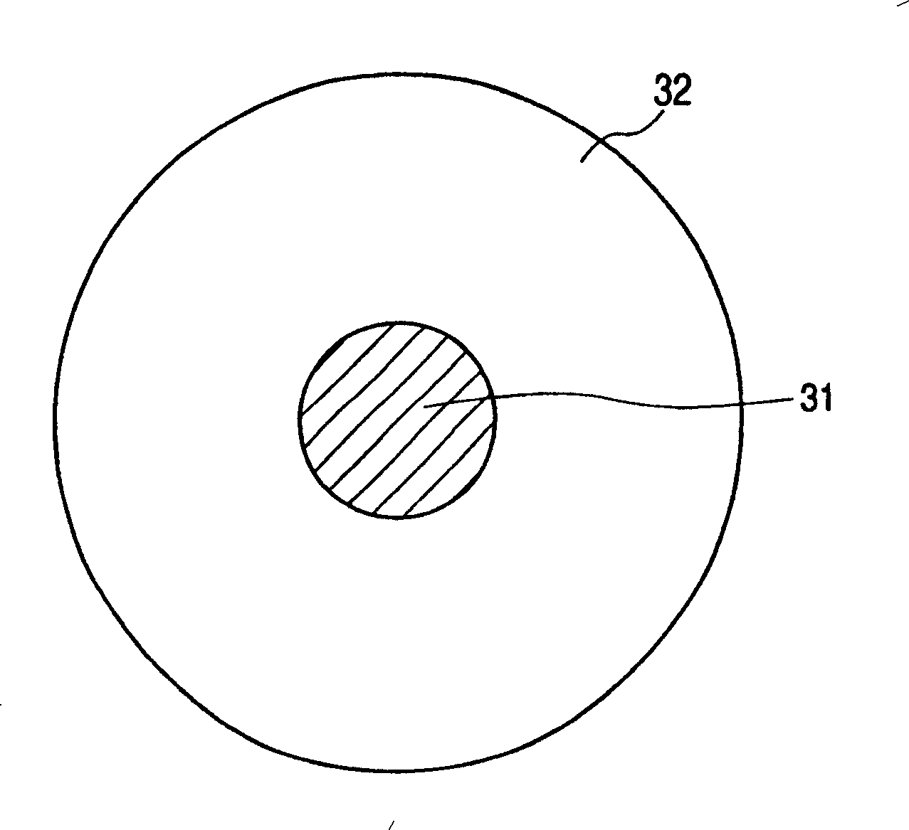
[0093] Follow the steps below to make a image 3 A transfer roller of the configuration shown.

[0094] A conductive cylindrical base material (metal core) 31 made of stainless steel with a diameter of 8 mm was prepared. In addition, the materials described below were mixed into a conductive elastic layer material with a pressure kneader.

[0095] · NBR (33.5% nitrile component) 76 parts

[0096] (Trade name: Nipol DN 214; manufactured by Japan Zeon Co., Ltd.)

[0097] ・Alkyl ether polymer (trade name: ZSN8030, manufactured by Japan Zeon Co., Ltd.) 20 parts

[0098] ・Epichlorohydrin rubber (trade name: EPICHLOMER H, manufactured by Daiso Co., Ltd.) 4 parts

[0099] · Zinc oxide 5 parts

[0100] ·Stearic acid 2 parts

[0101] · Hydrotalcite (hydrotalcite) 3 parts

[0102] · 20 parts of calcium carbonate

[0103] The NBR has the above formulas (A-1) and (A-2) as monomer units, and the copolymerization ratio (molar ratio) of (A-1) and (A-2) is 33.5:66.5. In addition, the...

Embodiment 2

[0124] A charging roller was obtained in the same manner as in Example 1, except that 64 parts of NBR, 6 parts of epichlorohydrin rubber, and 30 parts of alkyl ether polymer were used. The resistance value of the obtained charging roller was 2.80×10 7 Ω. In addition, its max. / min. value per revolution is 1.04. The hardness is 32.0°asker C.

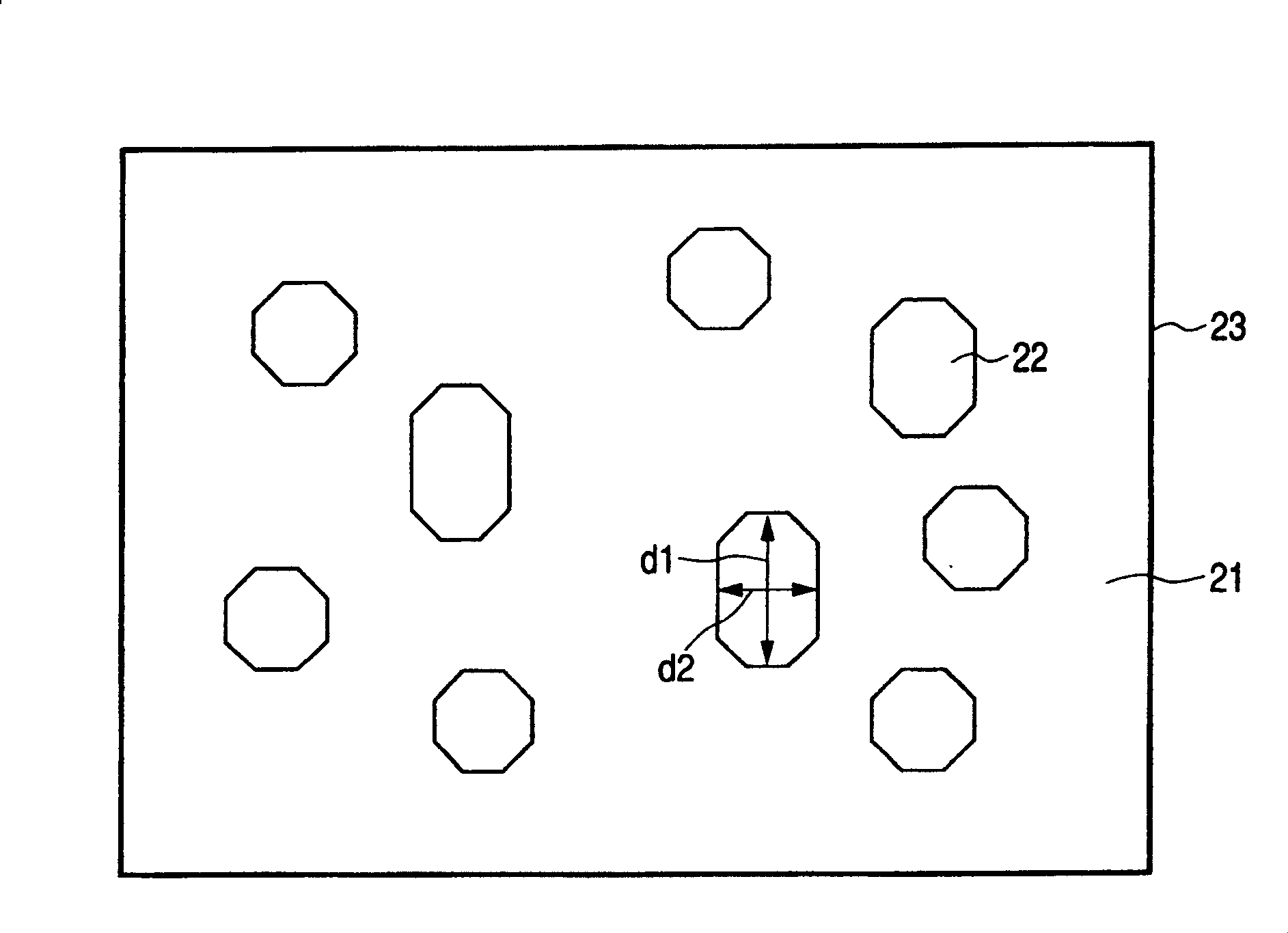
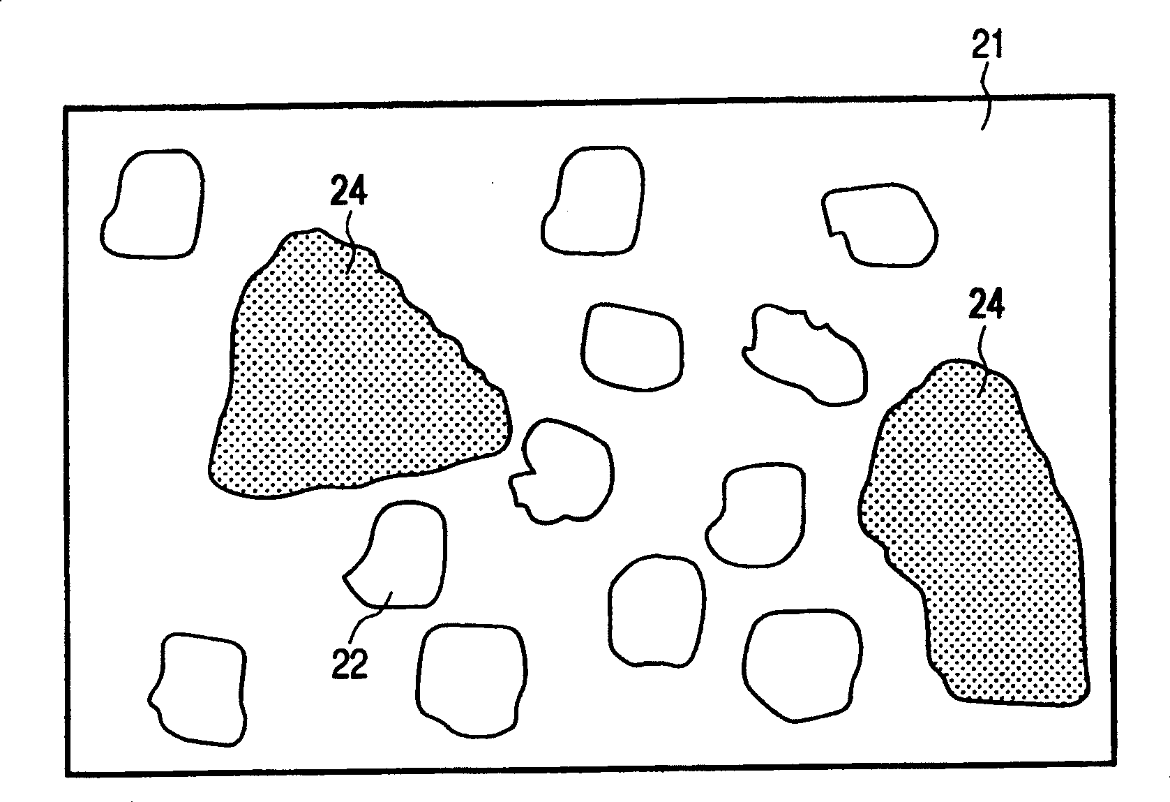
[0125] In addition, when the structure of the conductive elastic layer of this example was observed using a transmission electron microscope as in Example 1, it was found that it had a structure in which an island phase composed of an alkyl ether polymer was dispersed in a continuous phase composed of NBR. The average size of the island phases is 0.45 μm, and their average distance is 0.25 μm.

[0126] As in Example 1, the above charging roller was mounted on an electrophotographic device as a transfer roller, and the same evaluation as in Example 1 was performed using this electrophotographic device. As a result, a good image was obtai...

Embodiment 3

[0129] A charging roller was obtained in the same manner as in Example 1 except that 40 parts of NBR, 10 parts of epichlorohydrin rubber, and 50 parts of alkyl ether polymer were used. The resistance value of this charging roller is 7.81×10 6 Ω. In addition, its max. / min. value per revolution is 1.05. The hardness is 34.0°asker C.

[0130] As in Example 1, when the conductive elastic layer of this example was observed using a transmission electron microscope, it was found that NBR constituted a continuous phase and the alkyl ether polymer constituted an island phase. At this time, the average size of the island phase was 0.82 μm, and the average distance thereof was 0.32 μm.

[0131] In the same manner as in Example 1, the above-mentioned charging roller was mounted on an electrophotographic device as a transfer roller. With this electrophotographic device, when a solid black image was evaluated using a dry paper, a good image was obtained. Furthermore, when 500,000 sheets...


PUM


Abstract

The present invention relates to a charging member for charging a surface of a member to be charged in an image-forming apparatus, and one aspect of the present invention provides a charging member having an outermost surface layer containing a conductive elastic material. The conductive elastic material comprises a polymer including a polor polymer, and the poler polymer primarily comprises (i) acrylonitrile butadiene rubber; (ii) an ethylene oxide-propylene oxide-allyl glycidyl ether terpolymer; and (iii) a homopolymer of epichlorohydrin; and the weights x, y and z of the components (i), (ii) and (iii), respectively, has the relationship represented by the following expressions (1) and (2): 0.2<=Y / (x+y+z)<=0.5 (1) 4 G03G 5 / 06 G03G 21 / 18 4 22 1 2003 / 10 / 10 1497361 2004 / 5 / 19 100461006 2009 / 2 / 11 2009 / 2 / 11 2009 / 2 / 11 Canon K.K. Japan Kato Hisao Nishimura Yoshiaki Murata Atsushi yang hongjun 11277 Japan 2002 / 10 / 11 299045 / 2002

Description

technical field [0001] The present invention relates to a charging member used in an image forming device such as an electrophotographic device, and more specifically, to a charging member for charging the surface of a charged body in an image forming device such as an electrophotographic device. , a transfer member, a developing member, etc., and an image forming apparatus such as an electrophotographic device using the charging member, and an image forming process cartridge. Background technique [0002] In image forming devices such as electrophotographic devices (copiers, laser printers, etc.) and electrostatic recording devices, as a method of charging a charged body such as an electrophotographic photoreceptor or a dielectric, it is known that a charging member to which a voltage is applied is brought close to Or a contact electrification method in which the surface of the charged body is charged by contacting the charged body. Compared with corona electrification, co...

Claims


Application Information

Patent Timeline
Patent Type & Authority Patents(China)
IPC IPC(8): G03G5/06G03G21/18G03G15/02
CPCG03G15/0233Y10T428/31511Y10T428/31931
Inventor 加藤久雄西村芳明村田淳
Owner CANON KK
Why Eureka
Try Eureka