An energy saving biomass gasifying furnace

A gasifier and biomass technology, applied in incinerators, combustion methods, combustion types, etc., can solve problems such as air and water pollution, resource waste, pollution, etc., and achieve a large reduction in biomass and complete gasification and combustion. , the effect of reducing environmental pollution

Inactive Publication Date: 2009-03-04
SHENZHEN JUNENG BIOMASS GASIFICATION TECH
View PDF6 Cites 0 Cited by
  • Summary
  • Abstract
  • Description
  • Claims
  • Application Information

AI Technical Summary

Problems solved by technology

At present, the traditional utilization method is to burn biomass, but these traditional methods not only have low thermal efficiency, but also are labor-intensive and pollute seriously. Human health has adverse effects on ecology, society and economy. In addition, resources such as organic waste, organic waste residue, poultry manure and some agricultural waste are not fully utilized, which not only causes waste of resources, but also makes it a major In addition to causing serious air and water pollution, it also emits a large amount of greenhouse gases, which intensifies the global greenhouse effect
[0004] At present, in the development of biomass technology, problems often occur in tar treatment. For example, many projects are stopped due to tar blockage. In addition, the problem of low calorific value of gas will appear in development projects.

Method used


Image

  • An energy saving biomass gasifying furnace
  • An energy saving biomass gasifying furnace

Examples


Embodiment 1

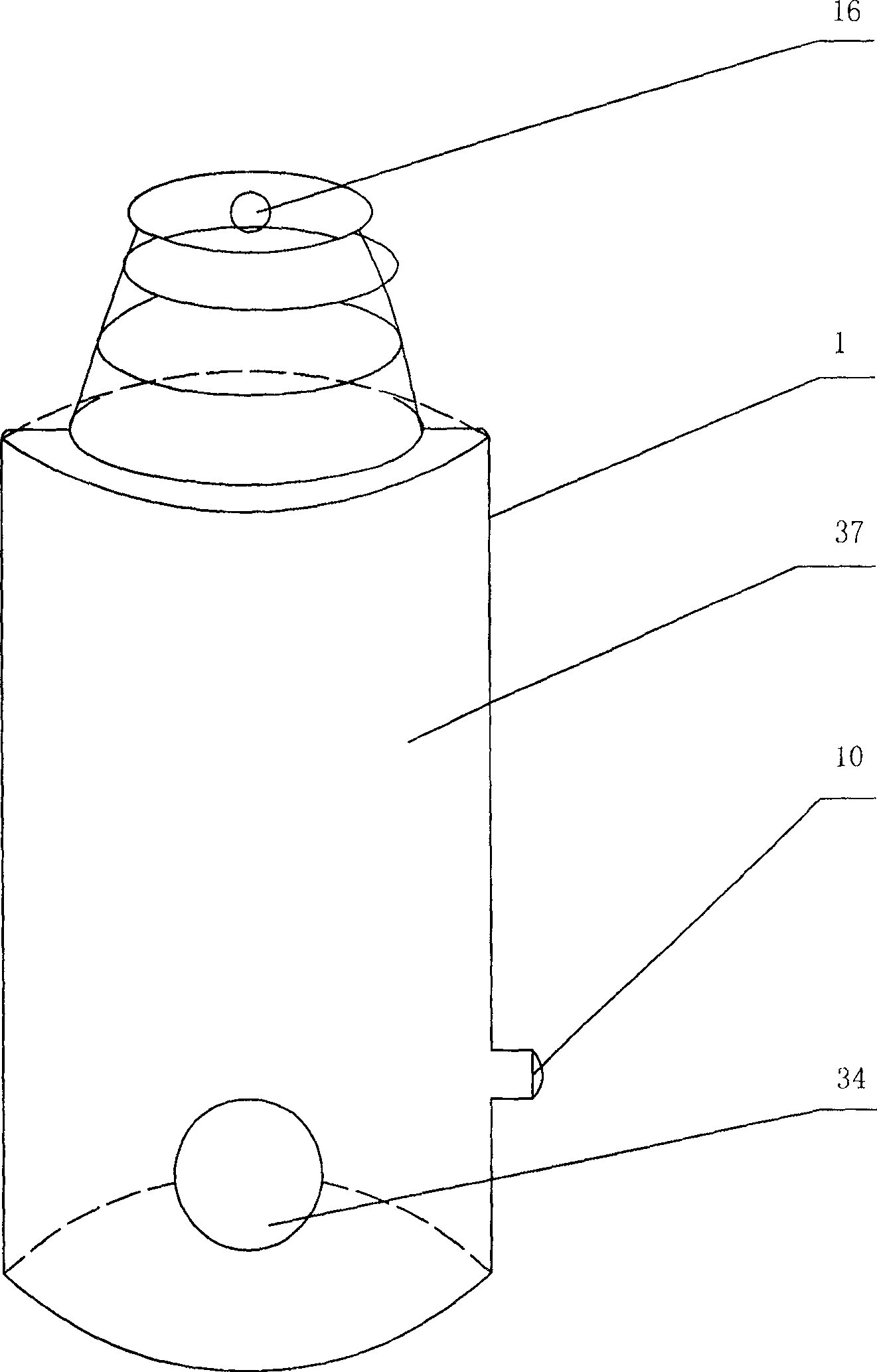
[0028] figure 1 It is a structural diagram of the present invention. In the figure, the feed port 16 of the present invention is arranged on the top of the furnace body 1, the furnace hearth 37 is in the furnace body 1, the slag outlet 34 is arranged on the bottom of the furnace body 1, and the furnace door 10 is arranged on the furnace body 1 on.

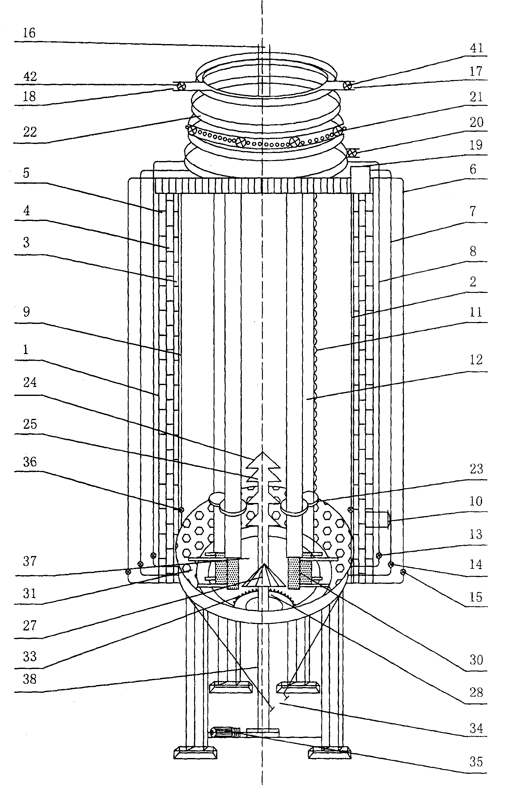
[0029] figure 2 It is a cross-sectional view of the present invention. In the figure, the present invention includes a spiral smoke box 22 arranged on the top of the furnace body 1, an electric distribution device 28 arranged in the furnace 37, a steam pipe 2, four secondary combustion fire pipes 12 and three Three air inlet pipes, that is, the three air inlet pipes are respectively the primary air inlet pipe 6, the secondary air inlet pipe 7, and the third air inlet pipe 8. The steam pipe 2 is provided with an electric valve 36, the primary air inlet pipe 6, and the secondary air inlet pipe. Electric valves 15, 14, and 13 are r...

Embodiment 2

[0042] The difference between this embodiment and the first embodiment is that there are twelve secondary combustion fire tubes 12 in this embodiment, and the effects achieved by this embodiment and the first embodiment remain the same.


PUM


Abstract

The energy saving biomass gasifying furnace has simple structure, convenient operation and less environmental pollution, and is used to treat various kinds of garbage and waste into fuel oil, fuel gas or other energy source material. Technologically, the energy saving biomass gasifying furnace includes a furnace body with material feeding port, furnace hearth, slag hole and furnace door; spiral smoke box on the furnace body; electrically driven material distributor, steam pipe, secondary burning pipe and air intake pipe inside the furnace hearth; electric valves, exhauster, and other parts.

Description

technical field [0001] The invention relates to the field of waste treatment devices, more specifically, it is an energy-saving biomass gasifier for treating and reusing various wastes and wastes. Background technique [0002] Biomass energy refers to various organisms produced by photosynthesis. Bioenergy is an energy form in which solar energy is stored in organisms in the form of chemical energy. It is an energy that uses biomass as a carrier. Biomassification is the use of plant stems, branches, leaves, straw, chaff, industrial solid organic waste, etc., to produce various combustible gases through anoxic combustion for various purposes. [0003] Biomass resources in the world are huge in quantity and in various forms, such as fuelwood, agricultural and forestry crops, agricultural and forestry residues, leftovers from food processing, garbage and waste, etc. At present, the traditional utilization method is to burn biomass, but these traditional methods not only have l...

Claims


Application Information

Patent Timeline
Patent Type & Authority Patents(China)
IPC IPC(8): F23G5/14
Inventor 王玉志徐淑萍
Owner SHENZHEN JUNENG BIOMASS GASIFICATION TECH
Why Eureka
Try Eureka