Surface film coating modify method for improving lithium ionic cell positive pole safety
A lithium-ion battery and surface coating technology, which is applied in ion implantation plating, electrode manufacturing, sputtering plating, etc., can solve the problems of safety, high battery specific energy, etc., and achieve less damage, dense coating layer, and simple equipment Effect
- Summary
- Abstract
- Description
- Claims
- Application Information
AI Technical Summary
Problems solved by technology
Method used
Image

Examples
Embodiment 1
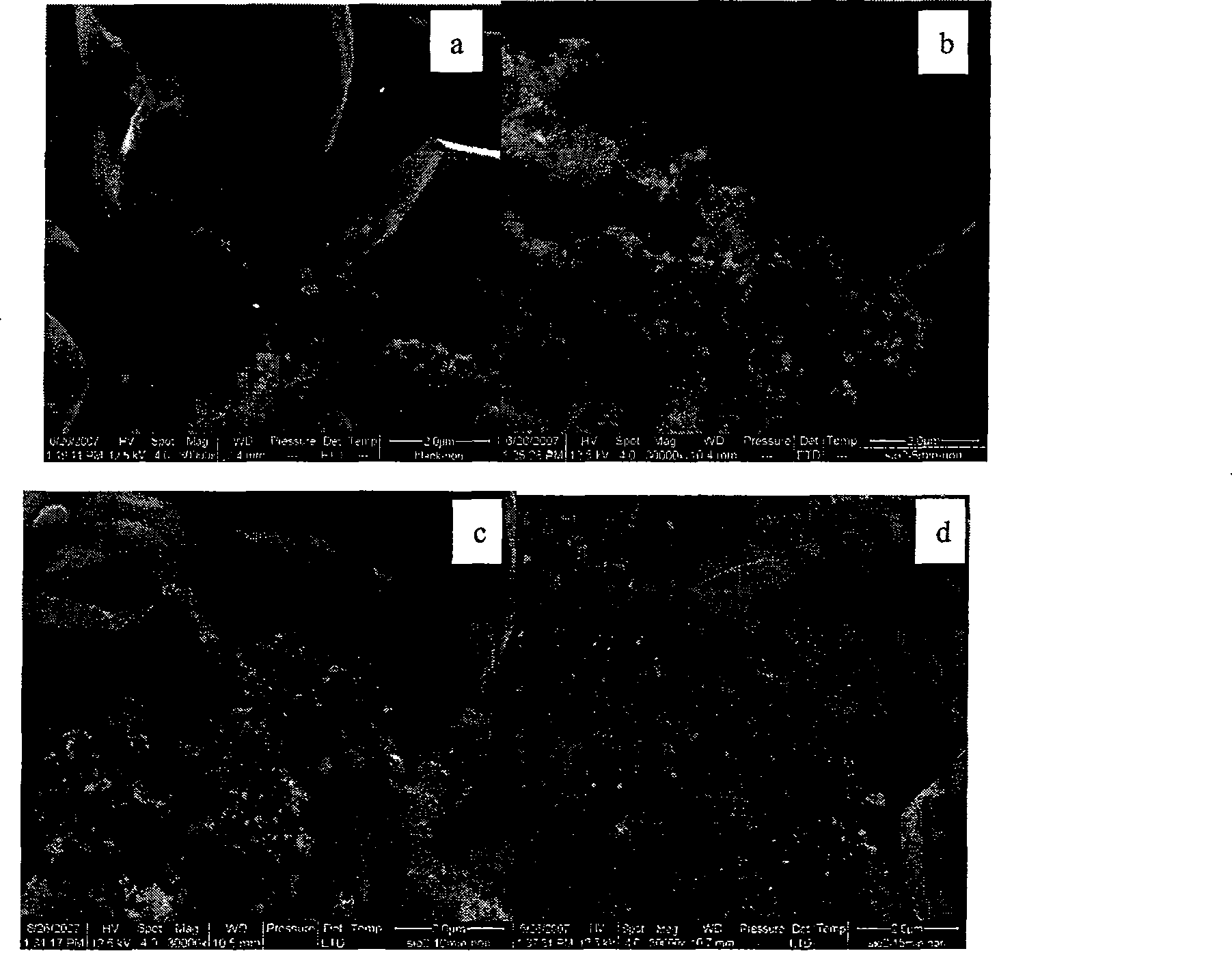
[0025] Select 0.2g of lithium cobalt oxide as the active material of the positive electrode material, add 0.0235g of conductive agent acetylene black into the mortar, add 0.0117g of binder polyvinylidene fluoride (PVDF) and N-methyl-2-pyridinone As the solvent of the binder, the three are mixed into a slurry at normal temperature and pressure, and evenly coated on the aluminum foil substrate as a current collector. The thickness of the obtained film is about 40 μm. After vacuum drying at 55 ° C for 12 hours, Compress under 0.2MPa, and then cut the baked pole piece into 20×20mm for later use. Put the cut pole piece into the sample chamber of the magnetron sputtering equipment. SiO 2 The target material is placed in the sputtering chamber of the magnetron sputtering equipment. Adjust the air pressure of the magnetron sputtering equipment to 0.5Pa, and adjust the power to 40W. Set the sputtering time to 5min and start running the equipment to coat the sample. See figure 1 , ...
Embodiment 2
[0027] Put the 20×20mm spare positive pole piece coated in Example 1 into the sample chamber of the magnetron sputtering equipment. Put the CaO target as the target material into the sputtering chamber of the magnetron sputtering equipment. Adjust the air pressure of the magnetron sputtering equipment to 0.5Pa, and adjust the power to 40W. Set the sputtering time to 5min and start running the equipment to coat the sample.
Embodiment 3
[0029] Put the 20×20mm spare positive pole piece coated in Example 1 into the sample chamber of the magnetron sputtering equipment. Will Al 2 o 3 The target is placed in the sputtering chamber of the magnetron sputtering equipment. Adjust the air pressure of the magnetron sputtering equipment to 0.5Pa, and adjust the power to 40W. Set the sputtering time to 10min and start running the equipment to coat the sample.
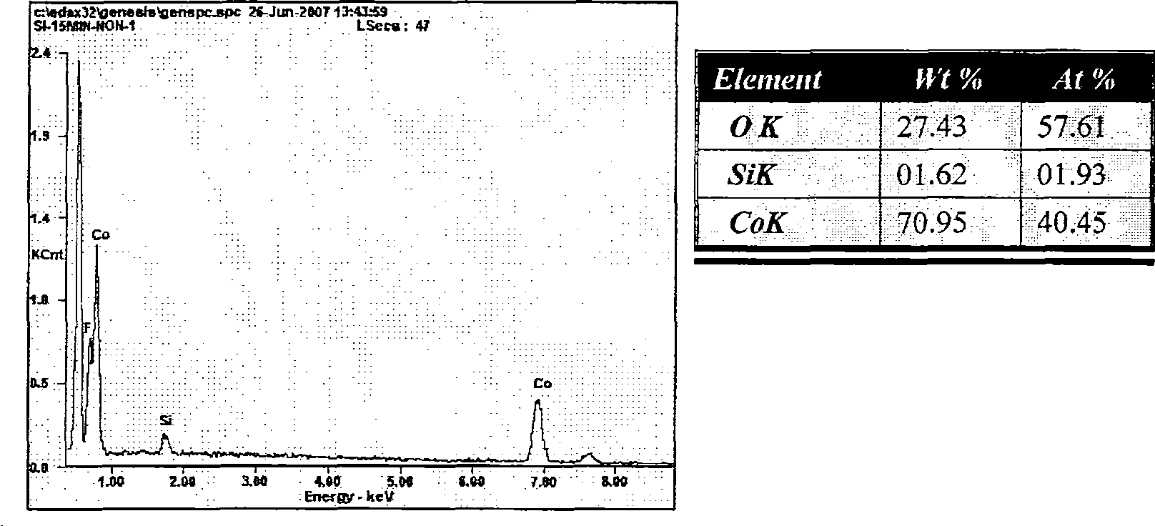
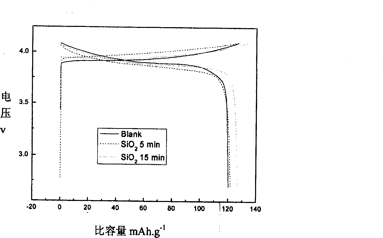
[0030] Analyzing the accompanying drawings, it can be known that the lithium-ion battery electrode pole piece after magnetron sputtering coating can be seen to form a coating layer on the surface. The positive electrode prepared by this method forms a protective film on the surface of the original electrode, and the film is stable and uniformly covers the electrode surface. It can also be seen from the accompanying drawings that the cycle performance, specific capacity, service life and thermal stability of the electrode piece after coating have all been improv...
PUM
| Property | Measurement | Unit |
|---|---|---|
| thickness | aaaaa | aaaaa |
Abstract
Description
Claims
Application Information
 - R&D
- Intellectual Property
- Life Sciences
- Materials
- Tech Scout
- Unparalleled Data Quality
- Higher Quality Content
- 60% Fewer Hallucinations
Browse by: Latest US Patents, China's latest patents, Technical Efficacy Thesaurus, Application Domain, Technology Topic, Popular Technical Reports.
© 2025 PatSnap. All rights reserved.Legal|Privacy policy|Modern Slavery Act Transparency Statement|Sitemap|About US| Contact US: help@patsnap.com