

Leadless PTC thermistor material with high Curie point
A thermistor and high Curie point technology, applied in the direction of resistors with positive temperature coefficients, inorganic insulators, ceramics, etc., can solve the problems of inability to realize semi-conductivity, improve the bonding force or grain boundary performance, and improve the performance of ceramics. performance, stability improvements
- Summary
- Abstract
- Description
- Claims
- Application Information
AI Technical Summary
Problems solved by technology
Method used
Image

Examples
Embodiment 1
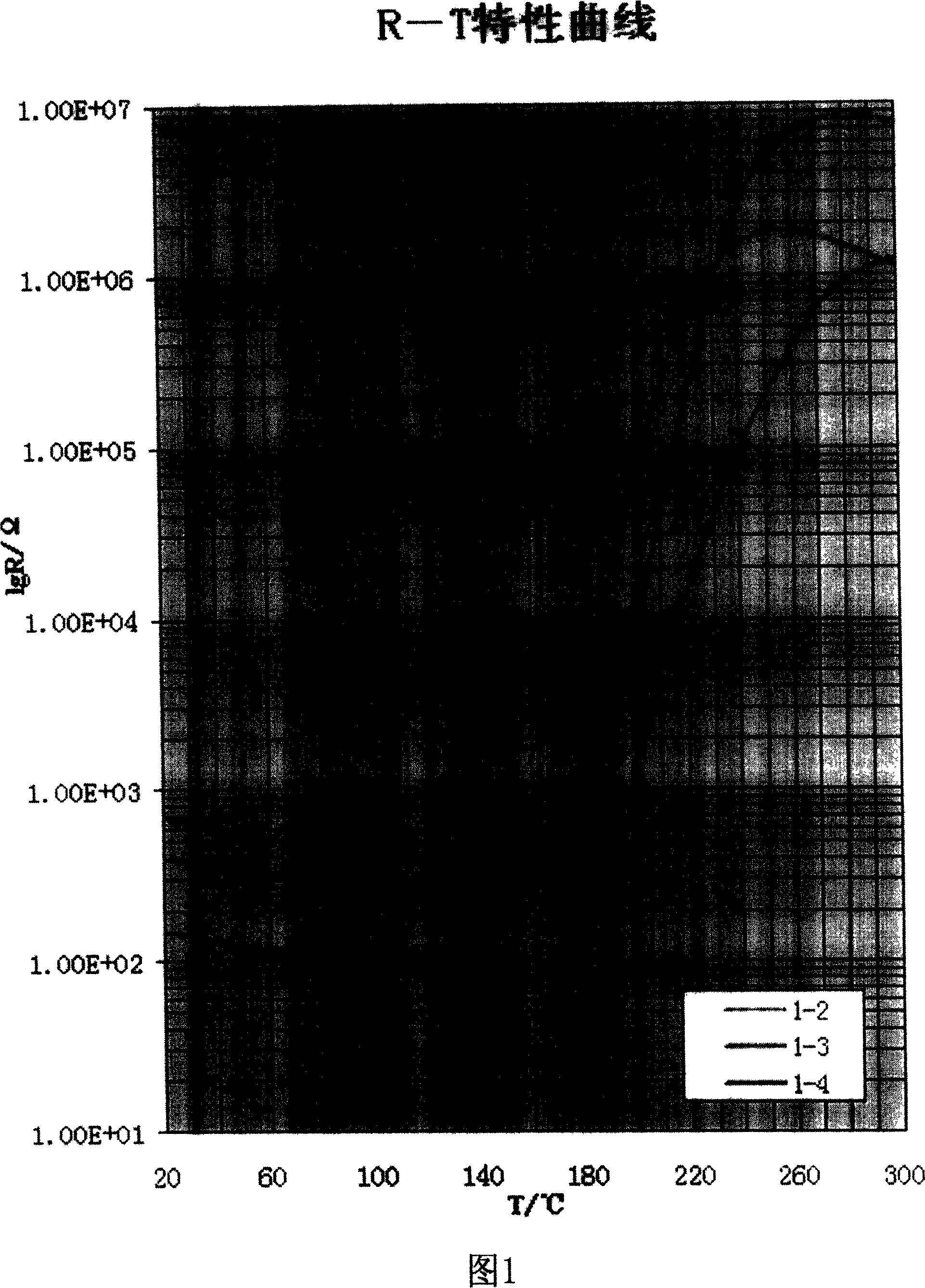
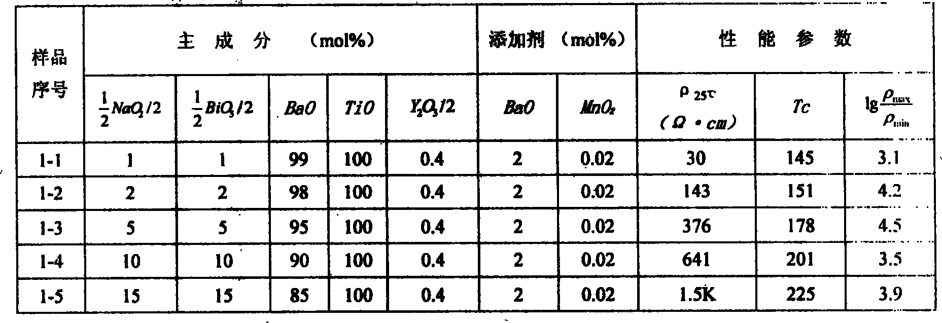
[0036] Example 1: As shown in Figure 1, the fixed semiconducting element of the resistance material in this example is Y, the addition amount is 0.4mol%, the additives are BaO 2mol%, MnO 2 0.02mol%, the raw materials weighed according to the production steps are: Y 2 O 3 0.450 g; BaCO 3 3.950 g; MnO 2 0.017 g; and then respectively with the pre-synthesized (Na 1 / 2 Bi 1 / 2 )TiO 3 2.12g, 4.24g, 10.59g, 21.19g, 31.78g; BaTiO 3 230.87g, 228.54g, 221.54g, 209.88g, 198.22g form a total of 5 groups of mixtures, ball-milled with deionized water for 24h, filtered, and dried at 100 °C to obtain powder materials, artificially granulated, and under 1.0 ton pressure The formed green body, the forming size is φ12×2.2mm, is sintered in a box furnace. During sintering, the furnace temperature is controlled first from room temperature to 600°C at a heating rate of 150°C / h, kept for 1h, and then at 250°C / h. The heating rate was increased to 1300 °C, kept for 1 h, and then the furnac...
Embodiment 2
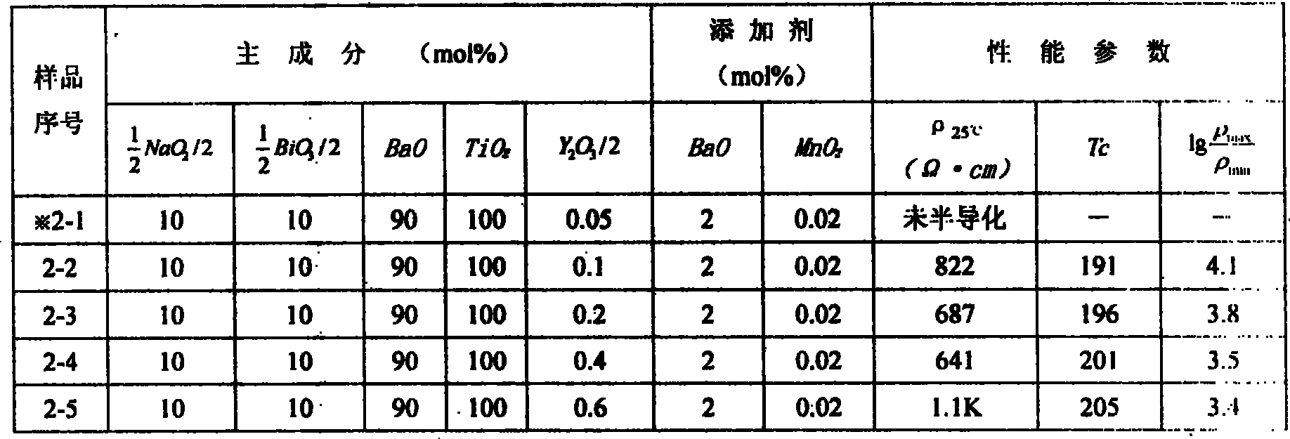
[0037] Example 2: The resistance material in this example is used to study the performance change of the sample by changing the amount of semiconducting elements added, and the pre-synthesized (Na1 / 2 Bi 1 / 2 )TiO 3 10mol%, BaTiO 3 90mol%, additive BaO 2mol%, MnO 2 0.02mol%, the raw material taken according to the production steps is: (Na 1 / 2 Bi 1 / 2 )TiO 3 21.19 g; BaTiO 3 209.88 g; BaCO 3 3.950 g; MnO 2 0.017 g; then separately with Y 2 O 3 0.055g, 0.115g, 0.225g, 0.450g, 0.660g to form a total of 5 groups of mixtures, ball milled with deionized water for 24h, filtered, and dried at 100 °C to obtain powder materials, artificially granulated, at a pressure of 1.0 tons The lower-formed green body, with a forming size of φ12×2.2mm, is sintered in a box furnace. During sintering, the furnace temperature is firstly grown from room temperature to 600°C at a heating rate of 150°C / h, kept for 1 hour, and then heated at 250°C / h. The heating rate of h was raised to 1300 ...
Embodiment 3
[0038] Example 3: The resistive material in this example was used to study the effect of changes in the types of semiconducting elements on the properties of the samples. Fix the pre-synthesized (Na 1 / 2 Bi 1 / 2 )TiO 3 10mol%, BaTiO 3 90mol%, additive BaO 2mol%, MnO 2 0.02mol%, the raw materials weighed according to the production steps are: BaCO 3 3.950 g; MnO 2 0.017 g; (Na 1 / 2 Bi 1 / 2 )TiO 3 21.19 g; BaTiO 3 209.88 g; then separately with the semiconducting element Y 2 O 3 0.450 g; La 2 O 3 0.650 g; Sb 2 O 3 0.580 g; Nb 2 O 5 0.530 g; Ta 2 O 5 A total of 5 groups of 0.88 g mixtures were formed, ball milled with deionized water as the medium for 24 hours, filtered, dried at 100 °C, artificially granulated, and formed into a green body under a pressure of 1.0 ton. The formed size was φ12 × 2.2 mm. Sintering in the furnace, control the furnace temperature from room temperature to 600 °C at a heating rate of 150 °C / h, hold for 1 hour, and then grow to ...
PUM
 Abstract
Description
Claims
Application Information