

Field optical fibre probe and its production
A technology of optical fiber probe and optical fiber, which is applied in the field of preparation of core components of optical precision instruments, can solve the problems that the shape of the probe is easily affected by external disturbances, the diameter of the probe tip is large, and the diameter of the tip is not small enough to achieve a smooth surface and Controllable, small tip diameter, easy-to-implement effect
- Summary
- Abstract
- Description
- Claims
- Application Information
AI Technical Summary
Problems solved by technology
Method used
Image

Examples
Embodiment 1
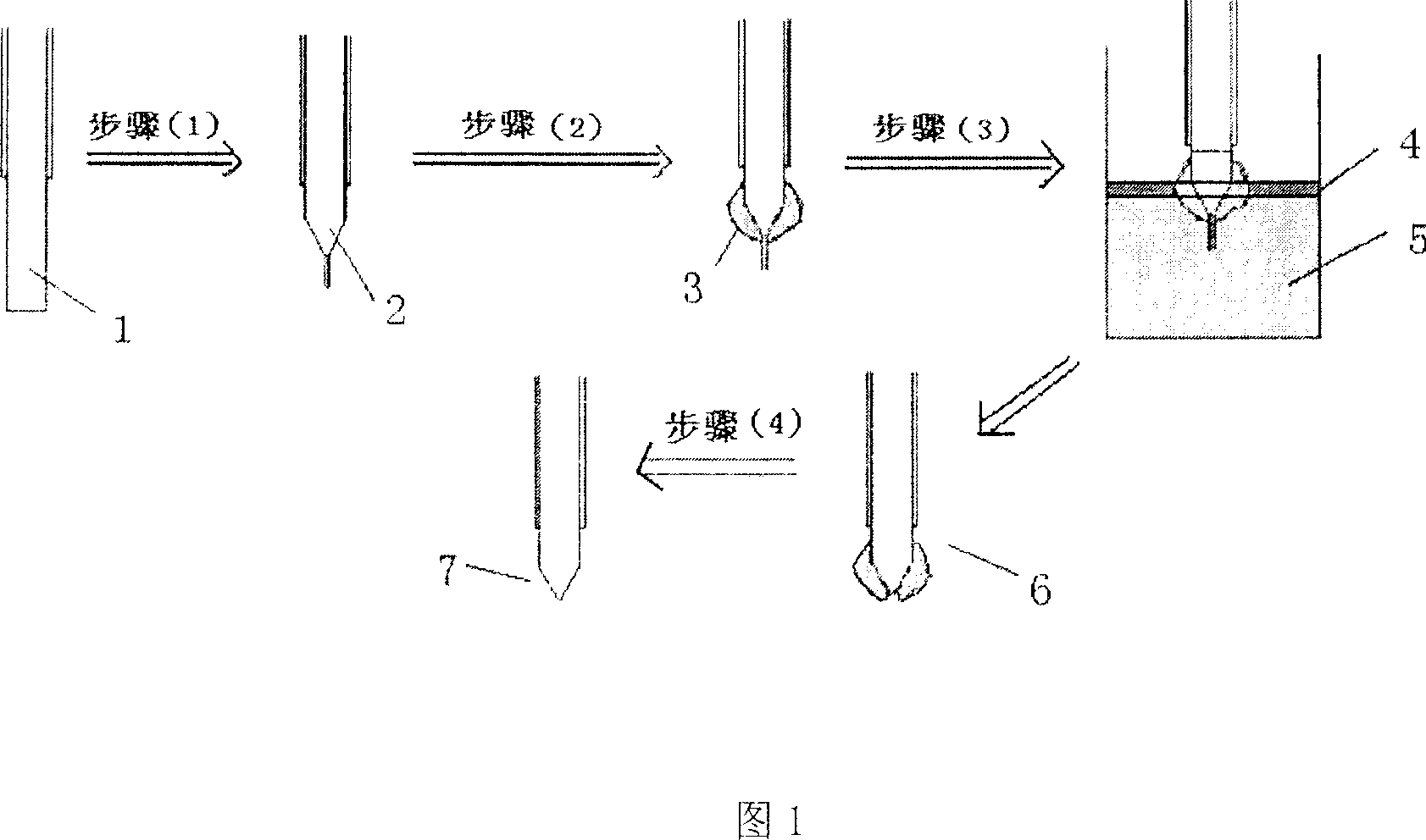
[0034] As shown in Figure 1, the probe preparation process of this embodiment is mainly divided into four steps:
[0035] The first step: the bare optical fiber 1 with the plastic protective layer removed within a few centimeters of the end is corroded with HF acid with a concentration of 40% at room temperature (24° C.) for 58 minutes to obtain a fiber with a certain cone angle and a diameter of the end. Bare optical fiber 2 after pretreatment and corrosion of 7 microns;
[0036] Step 2: Wrap the plastic solution obtained by dissolving the plastic with the organic solvent chloroform on the cone angle of the optical fiber and the bare part connected to the cone angle, and form a uniform plastic film 3 on the surface of the optical fiber after the chloroform volatilizes;
[0037] The above two steps belong to the pretreatment process before the optical fiber is corroded.
[0038] The third step: Insert the pretreated optical fiber into the liquid surface of 40% HF acid 5 with ...
Embodiment 2
[0042] In this embodiment and the following embodiment 3, the probe preparation process is the same as that of embodiment 1, the difference is that the corrosion parameters and the reduction degree of the optical fiber diameter are changed, thereby changing the shape of the final prepared probe.
[0043]Step 1: Corrode the bare optical fiber 1 from which the plastic protective layer has been removed within a few centimeters of the end with HF acid with a concentration of 30% at room temperature (24°C here) for 73 minutes to obtain a fiber with a certain cone angle and an end diameter Bare optical fiber 2 after pretreatment and etching for 16 microns;
[0044] The second step: wrap the PMMA solution obtained by dissolving the plastic (here polymethyl methacrylate, referred to as PMMA) with the organic solvent dichloromethane on the taper angle of the optical fiber and the exposed part connected to the taper angle, and wait until the dichloromethane After methane volatilizes, a ...
Embodiment 3
[0048] Step 1: Corrode the bare optical fiber 1 from which the plastic protective layer has been removed within a few centimeters of the end with HF acid with a concentration of 20% at room temperature (24°C here) for 77 minutes to obtain a fiber with a certain cone angle and a diameter of the end Bare optical fiber 2 after pre-etching to 25 microns;
[0049] Step 2: Wrap the plastic solution obtained by dissolving the plastic (here polymethyl carbonate) with the organic solvent tetrahydrofuran on the cone angle of the optical fiber and the bare part connected to the cone angle, and form a uniform plastic on the surface of the optical fiber after the tetrahydrofuran volatilizes. membrane 3;
[0050] The third step: Insert the pretreated optical fiber into the liquid surface of 20% HF acid 5 with an isooctane protective layer 4 to corrode. The corrosion is carried out at room temperature (24°C here). The time is 150 minutes;
[0051] Step 4: Take out the optical fiber 7 after...
PUM
| Property | Measurement | Unit |
|---|---|---|
| Thickness | aaaaa | aaaaa |
| Diameter | aaaaa | aaaaa |
| Cone angle | aaaaa | aaaaa |
Abstract
Description
Claims
Application Information