Optical fiber Fabry-Perot sensor and manufacture method therefore

A technology of Fap sensor and manufacturing method, which is applied in the direction of converting sensor output, using optical devices to transmit sensing components, instruments, etc., which can solve the problems of small contrast of sensor reflection stripes, low temperature resistance, and difficulty in large-scale manufacturing, etc., to achieve Save the manual packaging process, mechanical stability and high temperature resistance, and achieve the effect of large-scale manufacturing

Inactive Publication Date: 2007-09-12
冉曾令
View PDF2 Cites 40 Cited by
  • Summary
  • Abstract
  • Description
  • Claims
  • Application Information

AI Technical Summary

Problems solved by technology

[0004] In fiber optic sensors, the sensors for temperature, strain and pressure measurement are mainly fiber Bragg gratings (FBG) and FP cavity interferometers. FBG is widely used due to its temperature and other measured cross-sensitivity and spectral distortion under large strains. subject to greater restrictions
Due to the small cross-sensitivity between temperature and other measurands, the Fap sensor is very suitable for temperature, strain and pressure measurement, but the current structure of the optical fiber Fap sensor is shown in Figure 1, which uses a catheter 11 to connect two sections of optical fiber together , the mechanical stability is not good, and it is not resistant to high temperature. Its production mainly depends on manual production and packaging, and its yield and product repetition rate cannot be guaranteed.
[0005] JP2001280922 discloses a F-P sensor, which is only suitable for multi-mode optical fibers due to the use of corrosion technology, the sensor cavity must be multi-mode optical fibers, the production efficiency is low, and it is difficult to achieve large-scale manufacturing; Cutting, it is difficult to make a pressure sensor

Method used


Image

  • Optical fiber Fabry-Perot sensor and manufacture method therefore
  • Optical fiber Fabry-Perot sensor and manufacture method therefore
  • Optical fiber Fabry-Perot sensor and manufacture method therefore

Examples


Embodiment 1

[0033] Embodiment 1: Manufacture fiber optic Fabulous temperature, strain sensor

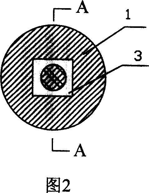
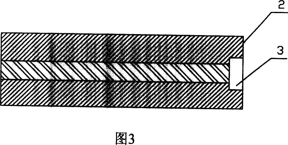
[0034] Step 1. Machining a cube-shaped microgroove 3 with a length of 10 microns and a width of 10 microns on the end face 2 of the single-mode silica fiber 1 with a depth of 30 microns, as shown in FIGS. 2 and 3 .

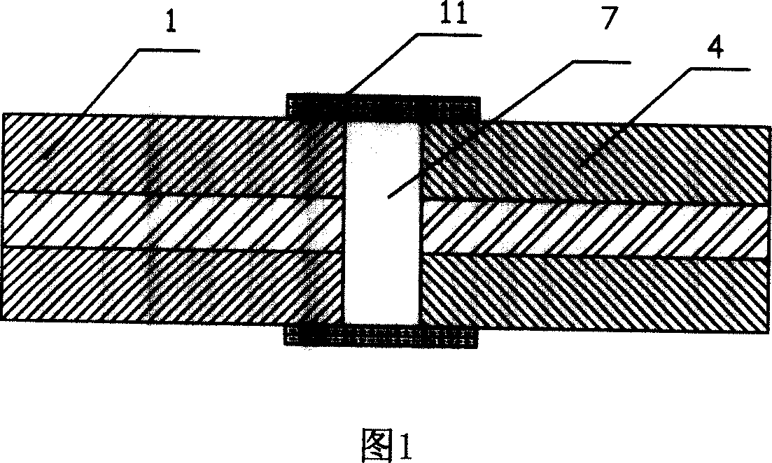
[0035] Step 2, outside the microgroove 3 of the quartz optical fiber 1 processed in step 1, a section of single-mode quartz optical fiber 4 is welded by an arc of an ordinary fusion splicer to form an optical fiber temperature and strain sensor, as shown in Figure 4, the optical fiber method The reflectance spectra of the temperature and strain sensors are shown in Figure 9, and the contrast of the reflective stripes is above 10dB.

[0036] When in use, the fabricated optical fiber Fab temperature and strain sensor can be packaged on the base material or used directly.

Embodiment 2

[0037] Embodiment 2: Manufacture fiber optic Fabulous temperature, strain sensor

[0038] Step 1. Process a cylindrical microgroove 3 on the end face 2 of the multimode gem fiber 1 with an ultraviolet laser, as shown in FIG. 5 .

[0039] Step 2. Connect a section of multimode gem fiber 4 outside the microgroove 3 of the multimode gem fiber 1 processed in step 1. A cylindrical microgroove 5 is processed on the end surface of the multimode gem fiber 4 . The micro-groove 3 and the micro-groove 5 are oppositely connected to each other to form an optical fiber Fappau temperature and strain sensor, as shown in FIG. 6 .

Embodiment 3

[0040] Embodiment 3: Manufacture fiber optic Fabulous temperature, strain sensor

[0041] Step 1. Process a cylindrical microgroove 3 on the end face 2 of the single-mode quartz optical fiber 1 with an ultraviolet laser.

[0042] Step 2, a section of single-mode quartz fiber 4 is fused outside the microgroove 3 of the silica fiber 1 processed in step 1 to form an optical fiber Fab temperature and strain sensor. The reflection spectrum of the optical fiber Fab temperature and strain sensor is shown in Figure 10 It shows that the contrast of reflection fringes is over 25dB.

[0043] When in use, the fabricated optical fiber Fab temperature and strain sensor can be packaged on the base material or used directly.


PUM

PropertyMeasurementUnit
Thicknessaaaaaaaaaa

Abstract

This invention relates to a good mechanical stability, high temperature resistant and good optical property optical fiber sensor, includes optical fiber and by-met optical fiber. optical fiber or / and by- met fiber optic end face have micro-flutes, and via butt joint together; The described micro-flute forms a FP cavity which has plain optical reflection surface. The invention adoptive laser machining craft can apply to every kind of optical fiber; be able to cutting optical fiber precisely, and are prone to execute different kinds of range's pressure sensor; optical property of the sensor is very fine; both the two stage optical fiber can be common single mode optical fiber, they are completely compatible; The contrast ratio of sensor's reflecting stripe can reach 10 dB upwards.

Description

technical field [0001] The invention belongs to the technical field of optical fiber sensing, and in particular relates to an optical fiber Farpert (FP) sensor and a manufacturing method thereof. technical background [0002] In recent years, with the rapid development of biology, medicine, energy, environment, aerospace, military and other fields, very urgent requirements have been put forward for the miniaturization, light weight, low energy consumption and harsh environment resistance of sensors. Micro-nano sensors It has become one of the major scientific and technological frontier hotspots in the world. The rapid development of laser microprocessing technology provides new technical means for the research of a new generation of micro-nano optical fiber sensor devices. Therefore, how to apply modern micro-nano processing technologies such as lasers to realize various micro-nano functional sensor devices on optical fibers is the key to the future development of optical fi...

Claims


Application Information

Patent Timeline
IPC IPC(8): G01J3/26G01B9/02G01K11/00G01L1/00G02B6/255
CPCG01J3/26G01D5/35312G02B6/34G02B6/02052G01D5/353G01L9/0079
Inventor 冉曾令饶云江
Owner 冉曾令
Why Eureka
Try Eureka