Production method for novel gyroscope signal reading graph

A manufacturing method and gyroscope technology, which are applied in the direction of rotating gyroscopes, semiconductor/solid-state device manufacturing, and photoplate-making process coating equipment, etc., can solve the problem of large damage to the surface performance of the rotor, insufficient straightness of the groove side of the line, and gyroscope Problems such as low precision of signal reading graphics production

Inactive Publication Date: 2008-02-20
INST OF ELECTRICAL ENG CHINESE ACAD OF SCI
View PDF1 Cites 4 Cited by
  • Summary
  • Abstract
  • Description
  • Claims
  • Application Information

AI Technical Summary

Problems solved by technology

[0006] The purpose of the present invention is to overcome the disadvantages of the existing gyroscope signal reading pattern, such as low manufacturing precision, large damage to the surface performance of the rotor, and insufficient steepness of the side of the line groove, etc., and propose a method of adding ion by sputtering coating and ultraviolet lithography. The microfabrication method of beam oblique incident etching greatly improves the signal reading pattern size accuracy and pattern edge profile resolution of the gyroscope detection surface with a uniform multi-groove grating structure, thereby improving the gyroscope measurement accuracy

Method used


Image

  • Production method for novel gyroscope signal reading graph
  • Production method for novel gyroscope signal reading graph

Examples


Embodiment 1

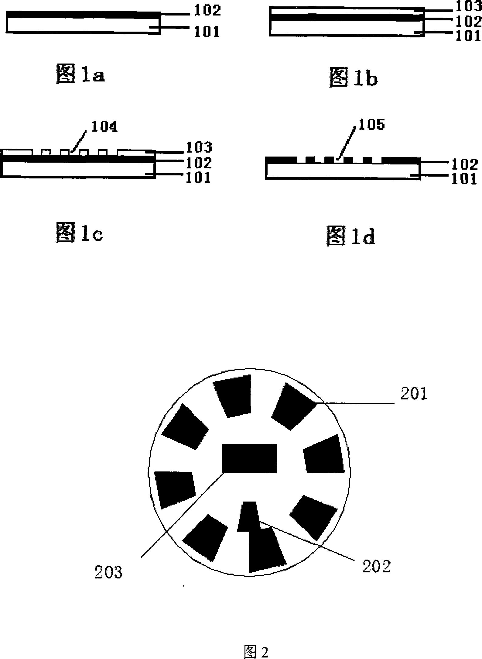
[0036]A metal thin film 102 is sputter deposited on the top plane 101 of the gyro rotor with a film thickness of 1 μm by using a magnetron sputtering coating method. The photoresist for spin-coating on the metal film is Ruihong RJZ-306, and the spin-coating speed is 2000rpm. After the photoresist is spin-coated on the metal film on the top plane of the rotor, the photoresist is pre-baked in an oven at a temperature of 100° C. for 60 seconds. Exposure was performed for 30 seconds by using an ultraviolet lithography machine, and a mercury lamp light source with a wavelength of 435 nm was used as the exposure light source. The photoresist is then post-baked at a temperature of 90° C. for 60 seconds. Then develop with RZX-3038 developer, and soak in the developer at 20°C for 30 seconds. Post-bake the developed photoresist pattern at a temperature of 100° C. for 90 seconds to obtain the desired photoresist pattern 104 on the surface of the metal film. Using the photoresist patte...

Embodiment 2

[0038] A metal thin film 102 is sputter deposited on the top plane 101 of the gyro rotor with a film thickness of 1 μm by using a magnetron sputtering coating method. The photoresist for spin-coating on the metal film is Ruihong RJZ-306, and the spin-coating speed is 2000rpm. After the photoresist was spin-coated on the metal film on the top plane of the rotor, the photoresist was pre-baked in an oven at a temperature of 110° C. for 70 seconds. Exposure was performed for 40 seconds by using an ultraviolet lithography machine, and a mercury lamp light source with a wavelength of 435 nm was used as the exposure light source. The photoresist is then post-baked at a temperature of 100° C. for 70 seconds. Then develop with RZX-3038 developer, and soak in the developer at 22°C for 50 seconds. Post-bake the developed photoresist pattern at a temperature of 110° C. for 100 seconds to obtain the required photoresist pattern 104 on the surface of the metal film. Using the photoresist...

Embodiment 3

[0040] A metal thin film 102 is sputter deposited on the top plane 101 of the gyro rotor with a film thickness of 1 μm by using a magnetron sputtering coating method. The photoresist for spin-coating on the metal film is Ruihong RJZ-306, and the spin-coating speed is 2000rpm. After the photoresist is spin-coated on the metal film on the top plane of the rotor, the photoresist is pre-baked in an oven at a temperature of 120° C. for 90 seconds. Exposure was performed for 90 seconds by using an ultraviolet lithography machine, and a mercury lamp light source with a wavelength of 435 nm was used as the exposure light source. Then the photoresist is post-baked at a temperature of 120° C. for 90 seconds. Then develop with RZX-3038 developer, and soak in the developer at 23°C for 90 seconds. The developed photoresist pattern is post-baked at a temperature of 120° C. for 110 seconds to obtain the desired photoresist pattern 104 on the surface of the metal film. Using the photoresis...


PUM


Abstract

The utility model relates to a producing method for new gyroscope signal reading graphics, which achieves a micron-level signal reading graphic by a sputtering deposition, a photolithography and an ion beam etching. The utility model has the following processing steps: 1. gaining the metal film by sputtering on the top flat surface of the gyroscope rotor plane; 2. spin coating photoresist on the metal film; 3. gaining photoresist graphics by UV exposure and development; 4. conducting ion beam etching with an incident angle of 15 to 30 degrees to remove residual photoresist, and signifying metal signal reading graphics in the rotor.

Description

technical field [0001] The invention relates to a method for making a novel gyroscope signal reading pattern, in particular to a method for making a high-precision gyroscope signal reading pattern. Background technique [0002] The new gyroscope combines superconductivity and classical mechanics theory, which greatly improves the performance and measurement accuracy of the gyroscope. As a new generation of gyroscope, its appearance and application will make the precision of inertial navigation reach a new height. The rotor of the new gyroscope is a high-precision free rotor without contact with other components, and its measurement can only use non-contact measurement methods. The top plane of the rotor of the new gyroscope is engraved with a pattern of a specific shape. The signal reading system of the gyroscope uses a non-contact photoelectric sensor to read the signal generated by the diffuse reflection of the engraved line on the rotor surface to obtain the attitude inf...

Claims


Application Information

Patent Timeline
Patent Type & Authority Applications(China)
IPC IPC(8): G01C19/02G01C21/18G03F7/16G03F7/20G03F7/38G03F7/40G03F7/26
Inventor 胡新宁王秋良韩立戴银明黄天斌王晖
Owner INST OF ELECTRICAL ENG CHINESE ACAD OF SCI
Why Eureka
Try Eureka