Continuous surface micro-structure forming method based on microlens array

A micro-lens array and micro-structure forming technology, which is applied in micro-structure technology, micro-structure devices, manufacturing micro-structure devices, etc., can solve the problems of difficulty in making small-scale graphics and complicated processes, and achieve simple continuous surface structure forming technology Effect

Inactive Publication Date: 2008-02-20
INST OF OPTICS & ELECTRONICS - CHINESE ACAD OF SCI
View PDF0 Cites 23 Cited by
  • Summary
  • Abstract
  • Description
  • Claims
  • Application Information

AI Technical Summary

Problems solved by technology

[0004] The technical problem to be solved by the present invention is to provide a continuous surface microstructure forming technology based on a microlens array in view of the existing continuous surface microstructure forming technology that requires large-scale equipment, complex processes, and difficulties in making small-scale graphics. Structure forming method, which requires the use of large-scale equipment to prepare photolithographic masks, and also greatly simplifies the continuous surface structure preparation process

Method used


Image

  • Continuous surface micro-structure forming method based on microlens array

Examples


Embodiment Construction

[0028] The present invention will be described in detail below in conjunction with specific embodiments, but the scope of protection of the present invention is not limited to the following examples, and should include all content in the claims.

[0029] The mask pattern in the present invention is a periodic pattern, or is a non-periodic pattern, and the base material selection infrared material and visible light material also all have the same process steps, etc., so the present invention only provides an embodiment, and other implementation modes are the same as this implementation The examples are completely similar.

[0030] Concrete implementation steps of the present invention are as follows:

[0031] (1) Coating photoresist S1805 on the surface of the quartz substrate.

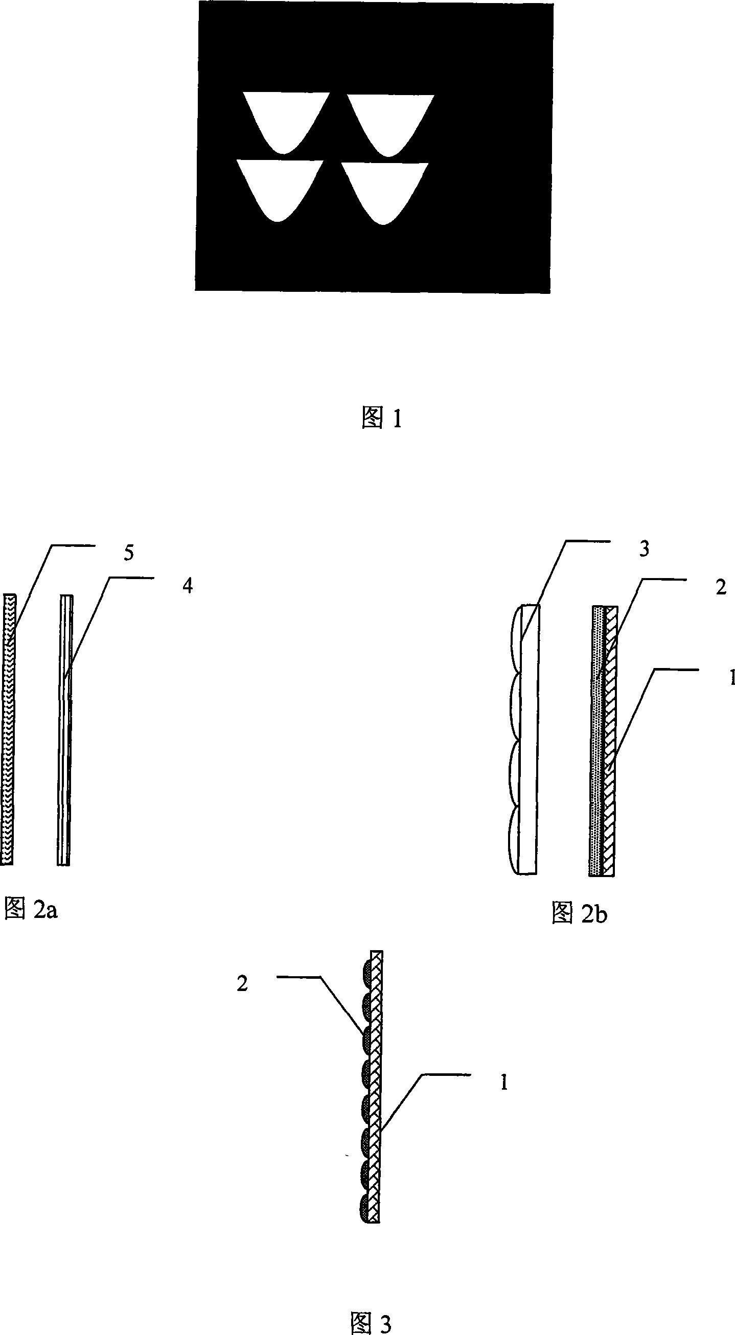
[0032] (2) Place the S1805 photoresist surface of the substrate and the mask pattern on the image plane and object plane of the microlens array respectively. The mask pattern is shown in Figure 1. The...


PUM


Abstract

The utility model relates to a forming method of continuous surface microstructure based on micro lens array; the technical proposal is that: the first step is to coat photoresist on a base surface; the second step is to arrange a photoresist plane and a mask pattern respectively on the image plane and object plane of the micro lens array; the third step is to arrange ground glass on the mask pattern and use scattered light produced by irradiating ground glass with the light source as exposure light source of the mask pattern; the fourth step is to reduce the projection lithography of the mask pattern and move the mask pattern or the substrate coated with photoresist or the micro lens array in process of exposure, so as to realize the continuous modulation of the surface light intensity of resists; the fifth step is to replace materials, adjust the relative position among the mask pattern, the micro lens array and the substrate coated with resists, and repeat the fourth step, so as to realize nesting lithography of different materials; the sixth step is to take out the substrate to be developed and obtain the required continuous surface microstructure. The utility model has the advantages of no need for large equipment to prepare lithography and mask, thus greatly reducing the complexity of the process.

Description

technical field [0001] The invention belongs to the technical field of micro-nano structure processing, in particular to a continuous surface-shaped micro-structure forming method based on a micro-lens array. Background technique [0002] In recent years, with the rapid development of micro-nano processing technology and nanomaterials, the electromagnetic properties of micro-nano metal structures are receiving more and more attention. The interaction of light with surface micro-nano metal structures produces a series of new and exotic physical phenomena. For example, in 1998, French scientist Ebbesen and his collaborators discovered the phenomenon of extraordinary enhancement (Extraordinary Optical Transmission) of light passing through a subwavelength metal hole array. The research of H.J.Lezec et al. further showed that: when the light passes through the sub-wavelength metal nanohole, its transmittance can not only be enhanced, but also the diffraction angle of the beam i...

Claims


Application Information

Patent Timeline
Patent Type & Authority Applications(China)
IPC IPC(8): G03F7/00G03F1/00G03F7/20B81C1/00
Inventor 杜春雷董小春刘强邓启凌
Owner INST OF OPTICS & ELECTRONICS - CHINESE ACAD OF SCI
Why Eureka
Try Eureka