Laser array micro-pore forming device and method

A molding device, micro-hole technology, used in laser welding equipment, welding equipment, metal processing equipment, etc.

Inactive Publication Date: 2008-04-30
SHANGHAI INST OF LASER TECH
View PDF0 Cites 52 Cited by
  • Summary
  • Abstract
  • Description
  • Claims
  • Application Information

AI Technical Summary

Problems solved by technology

[0003] The purpose of the present invention is to overcome the shortcomings of the existing semiconductor chip test probe card mechanical punching method, and to provide a laser arr...

Method used


Image

  • Laser array micro-pore forming device and method
  • Laser array micro-pore forming device and method
  • Laser array micro-pore forming device and method

Examples


Embodiment 1

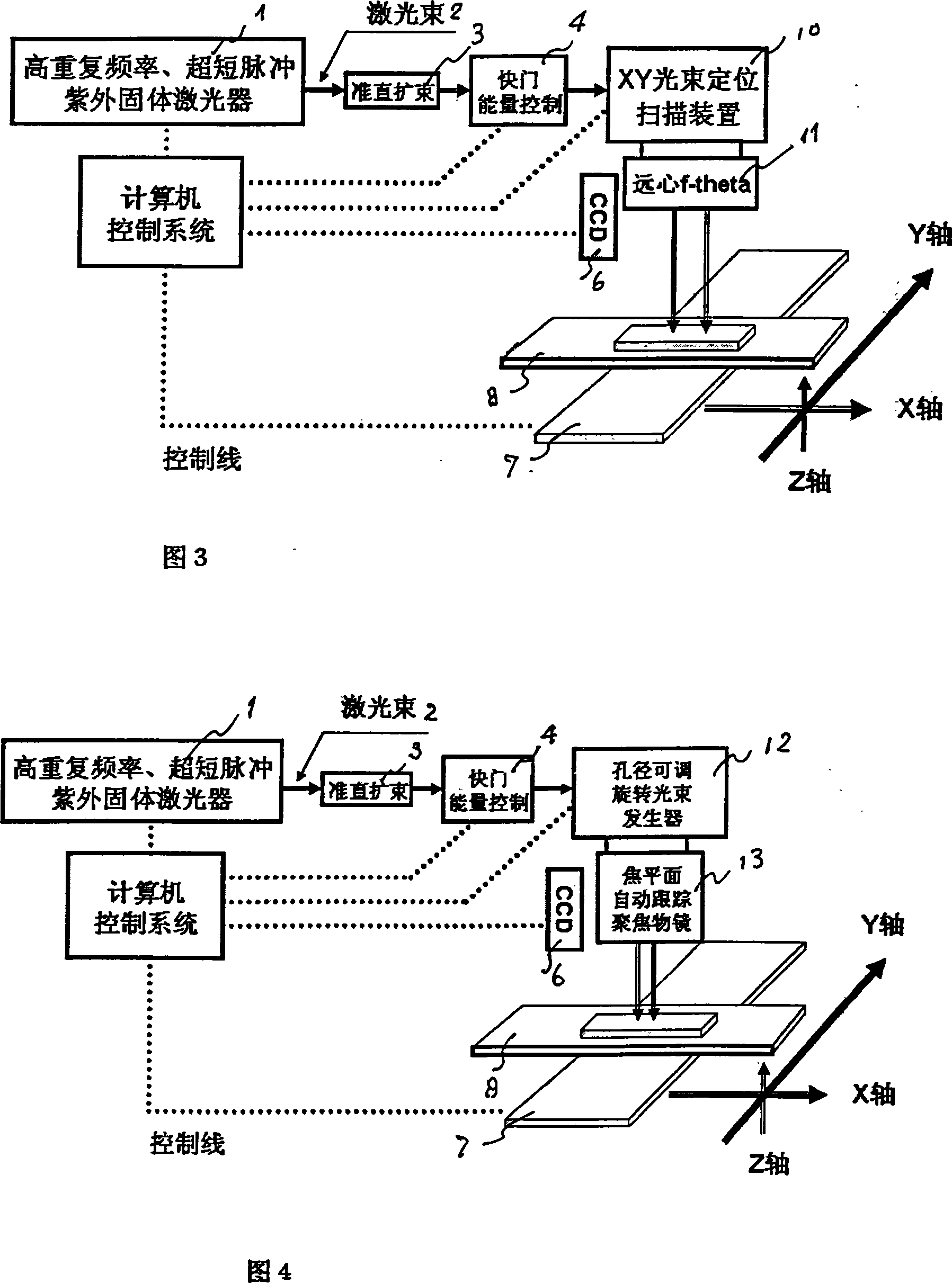
[0021] As shown in Figure 3, a laser array microhole forming device includes: high repetition rate, ultrashort pulse ultraviolet solid-state laser 1, laser beam generator 2, collimating beam expander 3, shutter 4 (laser energy controller ), the beam positioning and scanning device 5 is composed of an XY beam positioning scanner 10, a telecentric f-theta scanning focusing objective lens 11, a CCD vision alignment system 6, an XYZ (liftable) precision displacement work platform 7, a vacuum negative pressure Adsorption film rack 8, array of microporous workpieces 9.

Embodiment 2

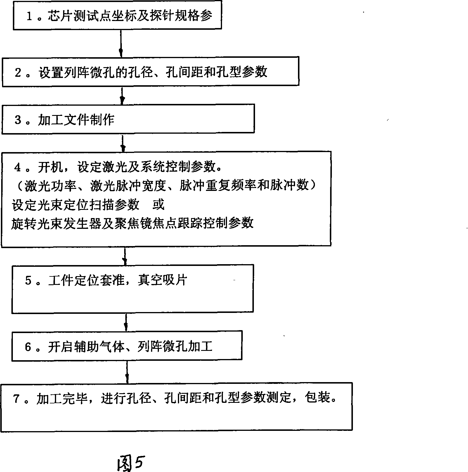
[0023] As shown in Figure 4, the laser array micro-hole forming device includes: a high repetition rate, ultra-short pulse ultraviolet solid-state laser 1, laser beam generator 2, collimating beam expander 3, shutter 4 (laser energy controller ), the beam positioning and scanning device 5 is composed of an adjustable aperture rotating beam generator 12, a focal plane automatic tracking and focusing objective lens 13, a CCD vision alignment system 6, an XYZ (liftable) precision displacement work platform 7, a vacuum negative pressure Adsorption film rack 8, array of microporous workpieces 9.

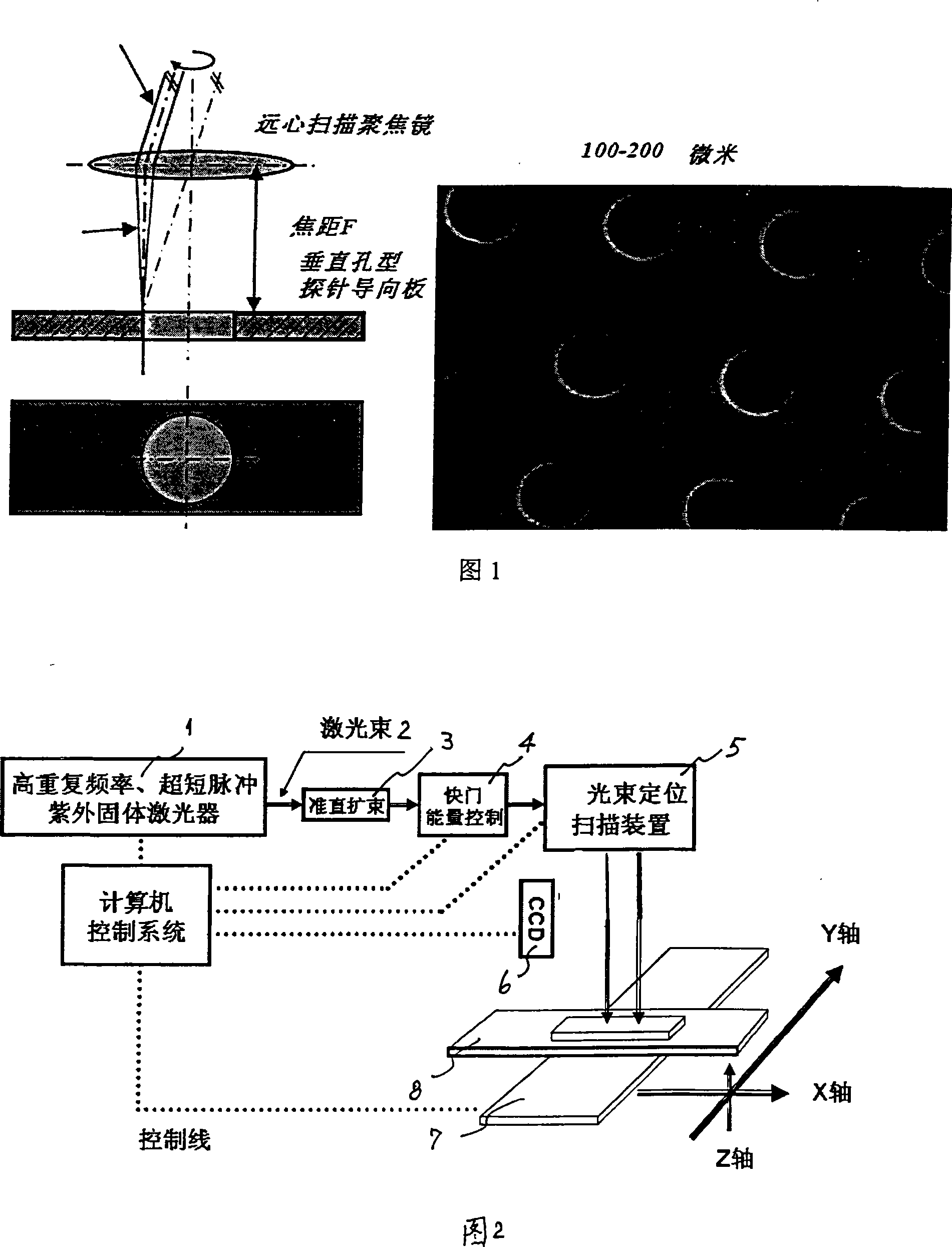
[0024] 1. Using telecentric f-theta focus scanning objective lens:

[0025] Set the required hole diameter, hole spacing and hole type parameters of the probe card array microplate, and make computer-controlled processing files: According to the required hole diameter, hole spacing, coordinate position and hole type parameters of the probe card array microplate , To form the control data file...


PUM


Abstract

The invention discloses laser-array pore molding devices and a method. The steps of the invention includes that, firstly, pore diameter, pore distance and caliber parameter of a pore plate are set, and a processing file is produced, secondly, laser power, pulse width, pulse repetition frequency and pulse count are set, thirdly, the parameter of light beam location scanning is set, fourthly, work-pieces are located, a visual system is located, and vacuum negative pressure absorbs a probe guide plate, fifthly, pressure and flow capacity of opening assistant gas are set, the processing is started, finally, the pore diameter, the pore distance and the caliber parameter are measured after the finishing of the processing. The laser-array pore molding devices include an ultraviolet solid laser with high repetition rate and ultrashort pulse, a laser beam generator, a collimation beam-expanding device, a shutter, a light beam location scanning device, a CCD visual location system, an XYZ displacement working platform, and a vacuum negative pressure absorbing-sheet frame. The invention has the advantages that the disadvantages of low efficiency, easy damage of a 'punch', changeable pore diameter and the like which exit in the present mechanical punching manner are overcome, dynamic digital hologram is directly pressed on the surface of the material of noble metal commemorative coins, thereby ensuring the esthetics of the commemorative coins.

Description

Technical field [0001] The invention relates to a laser array micro-hole forming device for precision laser drilling, processing array micro-holes on polymer dielectric insulating materials, and used for precision processing of array micro-holes of semiconductor chip test card probe guide plates in the integrated circuit industry And method. Background technique [0002] Laser micro-hole forming technology uses the characteristics of the interaction between laser beams and materials to micro-drill materials (including metals and non-metals). It involves multi-disciplinary integrated technologies such as light, mechanics, electricity, materials, control and detection. Laser drilling is widely used in high-tech industries such as automobiles, microelectronics, optical communications, aerospace, biomedicine, solar energy, and fuel cell new energy, and improves or replaces certain traditional processing methods. Different thermal energy processing from traditional infrared laser beam...

Claims


Application Information

Patent Timeline
IPC IPC(8): B23K26/38B23K26/02B23K26/14B23K26/04B23K26/382
Inventor 王又良潘涌张伟张宛平姜兆华沈冠群
Owner SHANGHAI INST OF LASER TECH
Why Eureka
Try Eureka