A laser light source device for laser display

A laser light source and laser display technology, which is applied in the direction of laser devices, semiconductor laser devices, lasers, etc., can solve the problems that hinder laser display from going to the market, the laser light source is large in size and low in reliability, and achieves simple structure, small size, The effect of high reliability

Inactive Publication Date: 2008-06-04
ACAD OF OPTO ELECTRONICS CHINESE ACAD OF SCI
View PDF2 Cites 6 Cited by
  • Summary
  • Abstract
  • Description
  • Claims
  • Application Information

AI Technical Summary

Problems solved by technology

[0007] However, the above-mentioned laser light sources include multiple parts such as semiconductor lasers, coupling systems, laser crystals, frequency doubling, and optical parameters, resulting in the disadvantages of large volume, high power consumption, low reliability, and high cost of laser light sources, which hinder the real development of laser display. market

Method used


Image

  • A laser light source device for laser display
  • A laser light source device for laser display

Examples


Embodiment 1

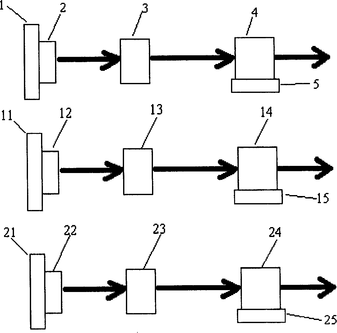
[0040] The laser light source device used for laser display in this embodiment is as figure 1 As shown, the first refrigerating sheet 1, the second refrigerating sheet 11 and the third refrigerating sheet 21 are respectively arranged on the red vertical surface-emitting semiconductor laser 2, the green vertical surface-emitting semiconductor laser 12 and the blue vertical surface-emitting semiconductor laser 22 without emitting light. On one side, the laser light emitted by each laser is perpendicularly incident on the corresponding first nonlinear frequency doubling crystal 4, second nonlinear In the frequency doubling crystal 14 and the third nonlinear frequency doubling crystal 24; wherein, all vertical surface emitting semiconductor lasers adopt vertical cavity surface emitting semiconductor lasers, and the diameter of the light emitting surface of each vertical cavity surface emitting semiconductor laser is 200 μm, red The output wavelength of optical VCSEL 2 is generally...

Embodiment 2

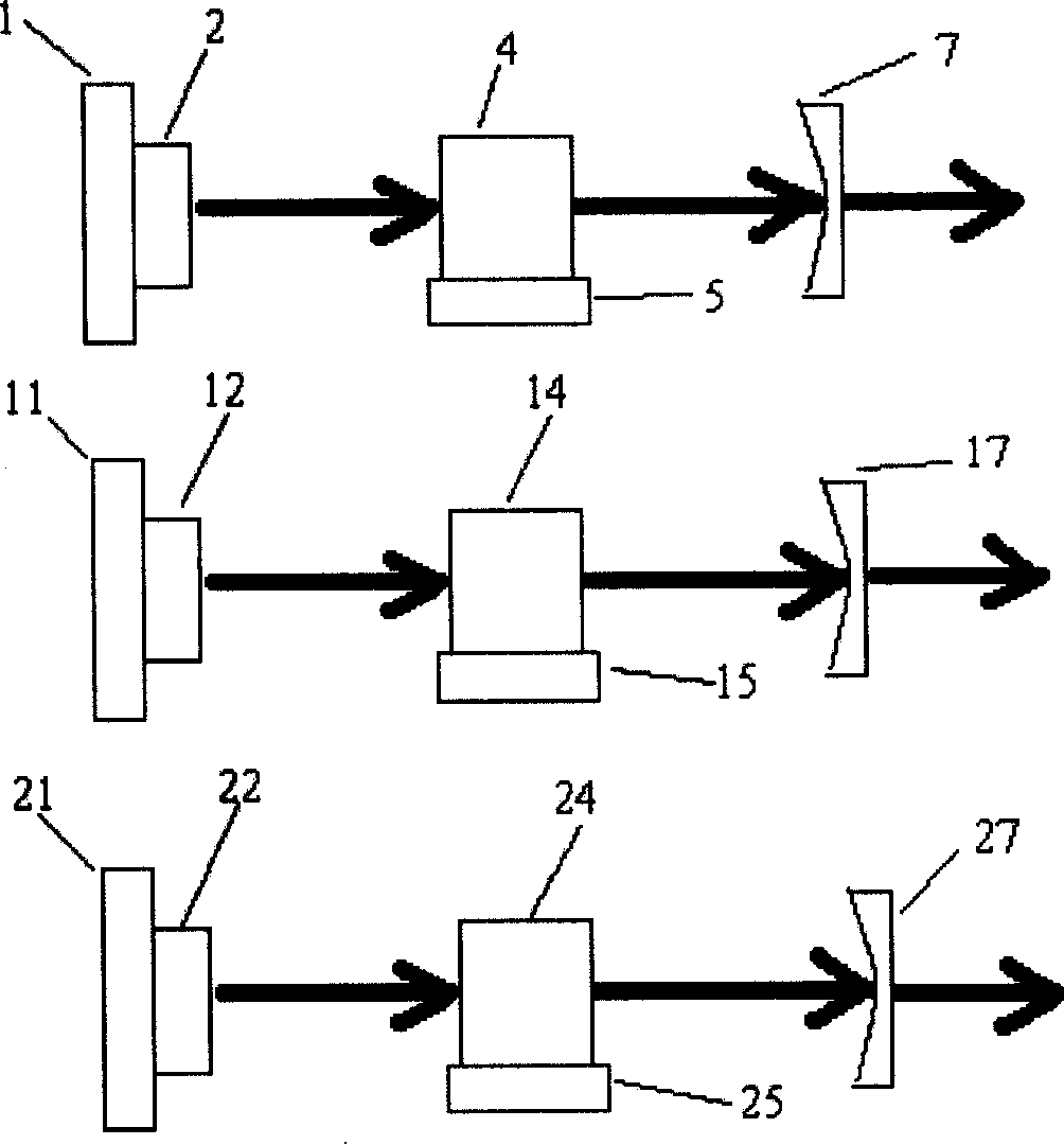
[0042] The laser light source device used for laser display in this embodiment is as figure 2 As shown, it also includes first, second, and third output mirrors. The output mirrors are selected from plano-concave lenses. The first cooling sheet 1, the second cooling sheet 11 and the third cooling sheet 21 are respectively arranged on the red light vertical surface emitting On the side where the semiconductor laser 2, the green vertical surface-emitting semiconductor laser 12 and the blue vertical surface-emitting semiconductor laser 22 do not emit light, the first, second, and third nonlinear frequency-doubling crystals 4, 14, and 24 are correspondingly arranged on each laser 2, 12, 22 on the light-emitting side, the laser light emitted by each laser is directly incident on the corresponding first nonlinear frequency doubling crystal 4, the second nonlinear frequency doubling crystal 14 and the third nonlinear frequency doubling crystal 24, after The laser beams emitted by ea...

Embodiment 3

[0046] Because the laser cavity direction of the vertical surface-emitting semiconductor laser is perpendicular to the semiconductor active layer, compared with the edge-emitting semiconductor laser, the light beam exits along the direction perpendicular to the substrate, so it is easy to integrate a two-dimensional array. In this embodiment, red Optical, green, and blue laser arrays replace the vertical external cavity surface-emitting semiconductor lasers 2, 12, and 22 in Embodiment 2, and adopt the first, second, and third volume Bragg grating mirrors as the first, second, and third volume Bragg grating mirrors. Three output mirrors, wherein each laser array is composed of 40 vertical external cavity surface-emitting semiconductor lasers or vertical cavity surface-emitting semiconductor lasers; and each volume Bragg grating mirror is made to have the fundamental frequency light of the corresponding frequency-doubled light wavelength. High reflectivity, high transmittance to ...


PUM


Abstract

The invention provides a laser source device used for laser display, which comprises laser generating devices of red light, green light and blue light and a first, a second and a third nonlinear frequency doubling crystals, which are respectively arranged on the outputting light paths of the laser generating devices of red light, green light and blue light. The invention is characterized in that: the laser generating devices of red light, green light and blue light respectively comprise at least one launching semiconductor laser with a vertical plane, wherein, the outputting wavelength of a launching semiconductor laser with a vertical plane of red light is 1,200nm-1,400nm; the outputting wavelength of a launching semiconductor laser with a vertical plane of green light is 1,000nm-1,100nm; the outputting wavelength of a launching semiconductor laser with a vertical plane of blue light is 880nm-980nm. Compared with the present laser display source, the invention requires no laser crystal and other complicated optical systems, thus having the advantages of simple structure, low cost and high reliability.

Description

Technical field: [0001] The invention relates to a laser light source device, in particular to a laser light source device for laser display. Background technique: [0002] Laser display has the advantages of large screen, high resolution, large color gamut, and high color saturation. It is a major development direction in the display field, and it is also one of the research and development hotspots in the international display field. It has application prospects in large-scale public media terminal display, entertainment performances and future families, and has great social and scientific value. [0003] At present, the red, blue and green primary color laser light sources for laser display are mainly produced by the following methods: [0004] The Chinese invention patent with the publication number CN1721963A uses a semiconductor diode laser (LaserDiode, hereinafter referred to as LD) to pump the laser crystal Nd:YVO4 at 808nm to produce a fundamental frequency light o...

Claims


Application Information

Patent Timeline
IPC IPC(8): H01S5/183H01S5/40H01S5/00G02F1/35G02B27/00G09F9/00H04N3/00
Inventor 周翊毕勇颜博霞赵江山
Owner ACAD OF OPTO ELECTRONICS CHINESE ACAD OF SCI
Why Eureka
Try Eureka