Nitrogen-containing compound luminescent material, manufacturing method and illuminating device used thereof

A technology of fluorescent materials and nitrogen compounds, applied in the direction of luminescent materials, chemical instruments and methods, electrical components, etc., can solve the problems of high manufacturing cost and low luminous brightness

Inactive Publication Date: 2008-06-11
DALIAN LUMINGLIGHT SCIENCE & TECHNOLOGY CO LTD
View PDF9 Cites 56 Cited by
  • Summary
  • Abstract
  • Description
  • Claims
  • Application Information

AI Technical Summary

Problems solved by technology

The effective excitation wavelength range of the fluorescent material in this method is increased, and the emission range can also be from green light to red light, but the luminous brightness of this fluorescent material is low, and the manufacturing cost is high. As a practical LED phosphor There are still great limitations in the use of

Method used


Image

  • Nitrogen-containing compound luminescent material, manufacturing method and illuminating device used thereof
  • Nitrogen-containing compound luminescent material, manufacturing method and illuminating device used thereof
  • Nitrogen-containing compound luminescent material, manufacturing method and illuminating device used thereof

Examples


Embodiment 1

[0062] raw material

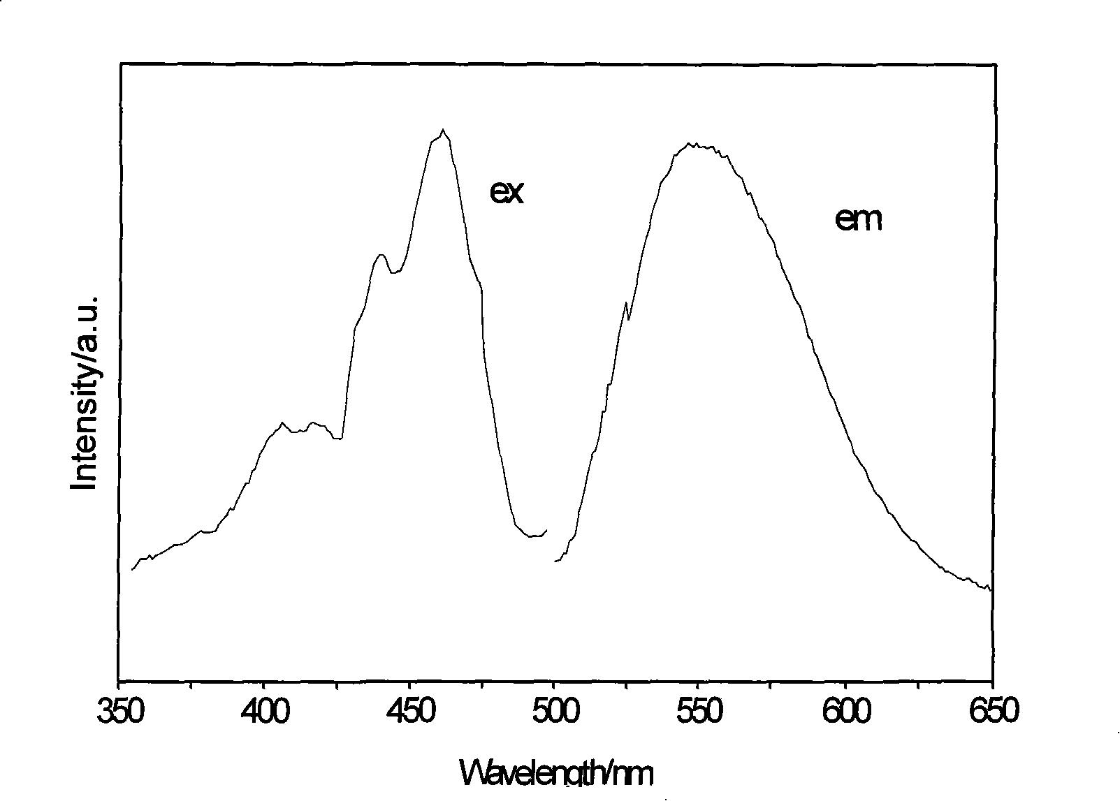
[0063] First, metal elemental Y and Ce are treated in flowing nitrogen at a temperature of 500 ° C to 1000 ° C to obtain Sr 3 N 2 and CeN precursor nitride components, followed by liquid SiCl in organic solvents 4 Reaction with ammonia gas, the filtered reaction product is subjected to reduction treatment between 300°C and 800°C to obtain active Si(NH) 2 components. Then, after weighing the above-mentioned components according to a certain molar ratio, they are fully ground and mixed uniformly. The above steps were all carried out under the protection of inert gas. Finally, put the mixture into a crucible, put it in an electric furnace, and 2 atmosphere (supplemented with a small amount of H 2 ) was calcined at 1200°C to 1600°C for 12 hours. After the sintered body is cooled, crush and grind, and then sieve with a 325-mesh sieve to obtain the fluorescent material Y with yellow-green luminescence in the present invention 2 Si 3 N 6 : Ce ...

Embodiment 2-8

[0064] Embodiment 2-8, preparation method and steps are the same as embodiment 1. The fluorescent materials of Examples 2-8 with yellow-green or yellow luminous colors were prepared by using the preparation method and steps for preparing the fluorescent material of Example 1. Table 1 shows the composition and luminous color of the fluorescent materials of each embodiment.

[0065] Table 1

[0066] Example

[0067] Example 7

Embodiment 9

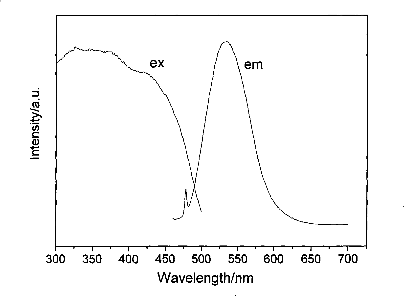
[0069] Firstly, metal elemental Ge and Eu are treated in flowing nitrogen at a temperature of 500 ° C to 1000 ° C to obtain Ge 3 N 2 and EuN precursor nitride components, followed by Ge 3 N 2 and EuN precursor nitride components and Ca 3 N 2 After weighing according to a certain molar ratio, fully grind and mix evenly. The above steps are carried out under the protection of inert gas. Finally, put the mixture into a crucible, put it in an electric furnace, and 2 atmosphere (supplemented with a small amount of H 2 ) was calcined at 1300°C to 1600°C for 10 hours. After the sintered body is cooled, it is pulverized and ground, and then sieved with a 325-mesh sieve to obtain the fluorescent material Ca with red light emission in the present invention. 2 GeN 2 :Eu 2 + . The excitation spectrum of the material is in the range of 300-550nm, the position of the main excitation peak is at 532nm; the position of the main emission peak is at about 625nm.

[0070] ra...


PUM


Abstract

The invention relates to fluorescent material including nitrogen compound. The fluorescent material can be stimulated through ultraviolet-blue green light, the general formula is MaAbQcOdNe:Ref, R1g and R2h, wherein, the M is selected from at least one of alkali metal, alkaline earth metal element of Zn, Lu, La, Y and Gd, the A is one element of B, Al, Ga, In, Y, Sc, P, As, Sb and Bi, the Q is one element of C, Si, Ge, Sn, Ti, Hf, Mo, W, P and Zr, the O is oxygen element, and the N is nitrogen element. The Re is at least one element selected from Eu, Nd, Dy, Ho, Tm, La, Ce, Er, Pr, Bi, Sm, Yb, Lu, Gd, Sb, Tb and Mn. The R1 is an ion selected from halogen, the R2 is an ion selected from NH4<+>, Au<+>, Ag<+>, Cu<+>, Li<+>, Na<+> and K<+>. The a, the b, the c, the d, the e, the f, the g and the h are mole coefficient.

Description

technical field [0001] The invention relates to a fluorescent material containing nitride, in particular to a fluorescent material for white light and multi-color light-emitting devices including semiconductor light-emitting elements (LEDs), which can be used as an excitation light source with an emission spectrum of 240-510nm The light-emitting element in the ultraviolet-blue-green light region is excited, absorbs at least a part of the light emitted by the excitation light source, and emits an emission spectrum in the range of 400-700nm, and belongs to the field of lighting technology, display and optoelectronics. Background technique [0002] The advent of blue, green, and white light-emitting diodes has made LED (semiconductor light-emitting diode, Light-Emitting Diode), known as "the technology that illuminates the future", gradually entering our daily life. As a new lighting technology, LED is triggering a revolution in the lighting field due to its flexible applicatio...

Claims


Application Information

Patent Timeline
Patent Type & Authority Applications(China)
IPC IPC(8): C09K11/78H01L33/00H01L33/50
Inventor 桑石云邓华夏威肖志国
Owner DALIAN LUMINGLIGHT SCIENCE & TECHNOLOGY CO LTD
Why Eureka
Try Eureka