Piping inside and outside communication device based on very low frequency power electromagnetic pulse
An electromagnetic pulse and communication device technology, applied in the field of communication, can solve problems such as undetectable operation and operation information, and achieve the effects of increased transmission distance and good applicability
- Summary
- Abstract
- Description
- Claims
- Application Information
AI Technical Summary
Problems solved by technology
Method used
Image
Examples
specific Embodiment approach 1
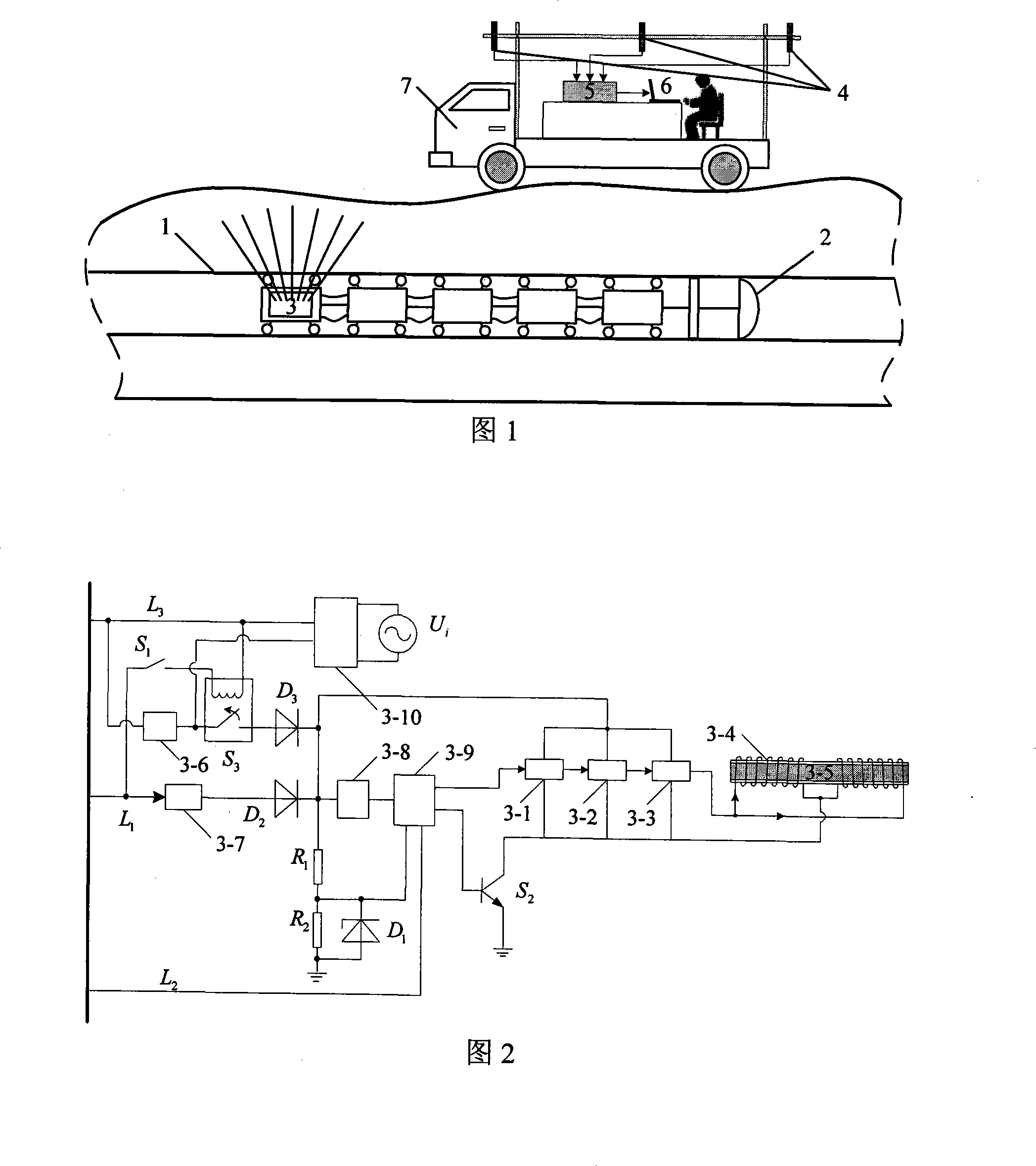
[0019] Specific implementation mode 1: This embodiment is described in conjunction with FIG. 1. This embodiment is composed of a very low frequency power electromagnetic pulse transmitter and its microcontroller 3, a magnetic induction receiving antenna group 4, a signal processing and transmission device 5 and a computer 6; The transmitting terminal of the power electromagnetic pulse transmitter and its microcontroller 3 emits a very low frequency power electromagnetic pulse signal, the magnetic induction receiving antenna group 4 receives the very low frequency power electromagnetic pulse signal and converts it into a voltage signal, and transmits it to the signal processing and transmission device 5 , The signal processing and transmission device 5 filters and amplifies the voltage signal, extracts the signal component with the same frequency as the transmitter, and transmits it to the computer 6 for data analysis and analysis of communication commands. The VLF power electromag...
specific Embodiment approach 2
[0020] The second embodiment: This embodiment will be explained with reference to Fig. 2. The difference between this embodiment and the first embodiment is that the VLF power electromagnetic pulse transmitter and its microcontroller 3 are composed of single-chip microcomputer 3-1 and D / A conversion 3-2. , Power amplifier 3-3, transmitting coil 3-4, magnetic core 3-5, backup battery 3-6, first voltage conversion module 3-7, second voltage conversion module 3-8, microcontroller 3-9, Battery charger 3-10, switch S 1 , Switch tube S 2 , Relay S 3 , Zener tube D 1 , The first diode D 2 , The second diode D 3 , The first resistance R 1 , The second resistor R 2 , 24V power cord L 1 , CAN communication line L 2 , Ground L 3 Composition; 24V power cord L 1 Connect the input terminal of the first voltage conversion module 3-7 and the switch S 1 The output terminal of the first voltage conversion module 3-7 is connected to the first diode D 2 The anode, the first diode D 2 The cathode is c...
specific Embodiment approach 3
[0025] Specific embodiment three: this embodiment is described with reference to FIG. 2. The difference between this embodiment and the specific embodiment two is that the transmitting coil 3-4 adopts distributed double-turn winding, which reduces the adverse effects caused by the coupling capacitance between the coils, and transmits The coil 3-4 is joined with alloy wire as a magnetic core to enhance the emission intensity of electromagnetic signals. Other components and connection modes are the same as in the second embodiment.
PUM
 Abstract
Description
Claims
Application Information
 - R&D
- Intellectual Property
- Life Sciences
- Materials
- Tech Scout
- Unparalleled Data Quality
- Higher Quality Content
- 60% Fewer Hallucinations
Browse by: Latest US Patents, China's latest patents, Technical Efficacy Thesaurus, Application Domain, Technology Topic, Popular Technical Reports.
© 2025 PatSnap. All rights reserved.Legal|Privacy policy|Modern Slavery Act Transparency Statement|Sitemap|About US| Contact US: help@patsnap.com


