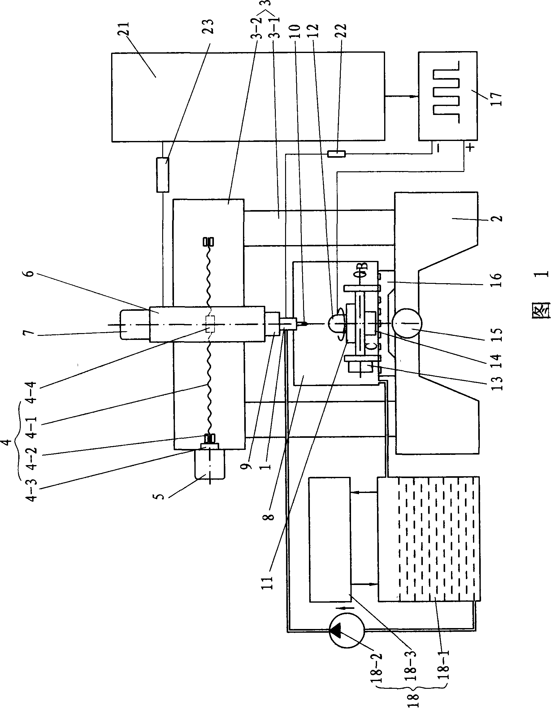
[0026] The embodiment shown in the drawings includes the bed 2, the frame 3, the horizontal worktable 16, the numerically controlled double-rotation worktable 11, the protective box 8, the spindle head 6, the electric spindle 9, the numerical control system 21, the pulse power supply 17, the electrolyte Circulation device 18.
[0027] The frame 3 is a gantry structure, and the frame 3 includes a column 3-1 and a beam 3-2.
[0028] The beam 3-2 of the frame 3 is provided with an X-direction transmission mechanism 4 and an X-direction servo motor 5, and the spindle head 6 is connected to the X-direction transmission mechanism 4. The X-direction transmission mechanism 4 has an X-direction ball screw transmission pair. The ball screw 4-1 in the X-direction ball screw transmission pair is supported by a pair of bearings 4-2 fixed on the beam 3-2, and the ball screw 4 One end of -1 is connected to the X-direction servo motor 5 by a coupling 4-3, and the spindle head 6 is connected to the nut 4-4 in the X-direction ball screw drive pair and is left and right along the guide rail on the crossbeam 3-2 mobile.
[0029] The spindle head 6 is provided with a Z-direction transmission mechanism and a Z-direction servo motor 7, and the electric spindle 9 is connected to the Z-direction transmission mechanism. The Z-direction transmission mechanism has a Z-direction ball screw transmission pair (not shown in the figure, please refer to the X-direction transmission mechanism). The ball screw in the Z-direction ball screw transmission pair is supported by a pair of bearings fixed on the spindle head 6. One end of the ball screw is connected to the Z-direction servo motor 7 by a coupling, and the electric spindle 9 is connected to the nut of the Z-direction ball screw transmission pair and moves up and down along the guide rail on the spindle head 6. The electric spindle 9 is insulated from the spindle head 6.
[0030] The bed 2 is provided with a Y-direction transmission mechanism and a Y-direction servo motor 15. The above-mentioned numerically controlled double-rotation workbench 11 is arranged on the horizontal workbench 16 and is connected with the Y-direction transmission mechanism. The Y-direction transmission mechanism has a Y-direction ball screw transmission pair (not shown in the figure, please refer to the X-direction transmission mechanism), and the ball screw in the Y-direction ball screw transmission pair is fixed on the bed 2 by a pair of Bearing support, one end of the ball screw in the Y-direction ball screw transmission pair is connected to the Y-direction servo motor 15 by a coupling. The horizontal table 16 is connected with the nut of the Y-direction ball screw transmission pair and runs along the bed. The guide rail on the body 2 moves back and forth. The CNC double-rotation table 11 adopts the URH-201-TNRP type CNC double-rotation table produced by UCAM in India. The horizontal table 16 is insulated from the numerical control rotary table 11, and the workpiece anode 12 is installed on the numerical control rotary table 16.
[0031] The electrolyte circulation device 18 includes an electrolyte tank 18-1, and the electrolyte pump 18-2 is connected to the pipeline between the electrolyte tank 18-1 and the electrolyte interface of the special cathode fixture 1. Temperature has a great influence on the machining accuracy, so the electrolyte tank 18-1 is provided with a temperature controller 18-3, and the temperature controller 18-3 can perform constant temperature control of the electrolyte in the electrolyte tank 18-1.
[0032] The protective box 8 is arranged on the horizontal workbench 16 and is located outside the numerical control double-rotation workbench 11. The protective box 8 collects the electrolyte, and the electrolyte is returned to the electrolyte tank 18-1 for recycling.
[0033] The electric spindle 9 is integrated with the special cathode fixture 1, and the electric spindle 9 drives the special cathode fixture 1 to rotate. The composite cathode 10 is fixed in the dedicated cathode fixture 1. The electric spindle 9 is purchased from the market.
[0034] figure 2 The dedicated cathode fixture 1 shown has a clamp body 1-1, the lower end surface of the clamp body 1-1 has an axial blind hole 1-1-1, and the lower half of the axial blind hole 1-1-1 is tapered The taper of the hole 1-1-4 and the tapered hole 1-1-4 is 7:22 to 26, and the embodiment adopts 7:24. The middle circumferential surface of the clamp body 1-1 is provided with an annular liquid inlet groove 1-1-2, and the bottom surface of the liquid inlet groove 1-1-2 is provided with 4 evenly distributed blind holes 1-1-1 leading to the axial direction The radial liquid inlet hole 1-1-3. The clamp body 1-1 is provided with a dynamic-fitting conductor 1-2 on the outer periphery of the middle part, and there is a relatively small clearance fit between the clamp body 1-1 and the conductor 1-2. The inner wall of the conductor 1-2 is provided with two annular sealing grooves and an annular mercury groove from top to bottom. Each of the annular sealing grooves is equipped with O-ring 1-5, and the mercury groove is filled with mercury to form a contact clip. 1 mercury circle 1-8. The conductor 1-2 is provided with a terminal hole, a liquid inlet hole 1-2-1 communicating with the liquid inlet groove 1-1-2 of the clamp, and a mercury injection threaded hole 1-2-2 communicating with the mercury groove. A terminal 1-7 is fixed in the column hole, and a water nozzle 1-6 is connected to the liquid inlet 1-2-1. The mercury is injected into the mercury tank through the mercury injection threaded hole 1-2-2. After the mercury injection is completed, the plug bolt 1-9 is screwed into the mercury injection hole 1-2-2 to prevent mercury leakage. The tapered hole 1-1-4 of the clamp body 1-1 is provided with a spring clamp sleeve 1-10 with a tapered top. The lower part of the clamp body 1-1 is provided with a thread, and the threaded part is provided with a clamping nut 1-11 , The bottom surface of the clamping nut 1-11 is provided with a cathode piercing hole 1-11-1. Rotating the clamping nut 1-11 can push the spring clamp 1-10 to move inside the clamp body 1-1, so that the lateral size of the spring clamp sleeve 1-10 is contracted to clamp the cathode 1-12. There is a double nut 1-3 on the clamp body 1-1 and above the conductor 1-2, and a plastic washer 1- on the clamp body 1-1 and between the conductor 1-2 and the double nut 1-3. 4. The plastic washer 1-4 is slightly elastic. After pressing the conductor 1-2, the conductor 1-2 and the clamp body 1-1 are in reliable contact in the axial direction when the conductor 1-2 and the clamp body 1-1 rotate relative to each other, thereby sealing the mercury. The double nut 1-3 can adjust and lock the axial position of the plastic washer 1-4.
[0035] The conductive terminal on the special cathode fixture 1 is connected to the negative electrode of the pulse power source 17 by a wire, and the workpiece anode 12 is connected to the positive electrode of the pulse power source 17 by a wire. The electrolyte interface on the dedicated cathode fixture 1 is connected to the output port of the electrolyte pump 18-2, and the circulating electrolyte provided by the electrolyte pump 18-2 is sprayed through the electrolyte nozzle of the composite cathode 10 with the electrolyte internal spray structure. To the machining surface of the workpiece anode 12, the working current is conducted through the workpiece anode 12, the electrolyte in the machining gap and the composite cathode 10, and the workpiece anode 12 is composite processed through electrochemical anode dissolution and mechanical grinding.
[0036] A high-precision small resistor 22 is connected to the wire between the terminal of the dedicated cathode fixture 1 and the negative electrode of the high-frequency narrow pulse pulse power supply 17. During the machining process, the machining current is detected by the high-precision small resistance 22. When the abrasive of the composite cathode 10 is worn or embedded with the machining product and short-circuited with the anode 12 of the workpiece, the composite cathode 10 retreats a certain distance and changes the polarity of the pulse machining power supply. In order to improve the performance, the composite cathode 10 is subjected to a short electrochemical processing to maintain a certain amount of abrasive grains protruding, and then feed processing. Due to the use of high frequency narrow pulse electrolysis power supply, the elimination of products in the machining gap is improved, and the surface quality of the workpiece is improved. Due to the use of non-linear passivation electrolyte, stray corrosion is reduced, so the machining accuracy is improved.
[0037] The electric spindle 9, the pulse power supply 17, the electrolyte pump 18-2 in the electrolyte circulation device 18, the X-direction servo motor 5, the Z-direction servo motor 7, the Y-direction servo motor 15, and the B rotation of the numerically controlled double-rotation table Both the motor 13 and the C rotary motor 14 are controlled by the numerical control system 21.
[0038] see image 3 The numerical control system 21 controls the rotation of the electric spindle 9 through the servo controller 23. The pulse power supply 17 and the electrolyte pump 18-2 in the electrolyte circulation device 18 are directly controlled by the numerical control system 21. The X-direction servo motor 5, Z-direction servo motor 7, Y-direction servo motor 15 and the B rotary motor 13 and C rotary motor 14 of the dual numerical control rotary table 11 all adopt AC servo motors, which are controlled by the numerical control system 21 in a semi-closed loop This kind of semi-closed loop system driven by AC servo motor has good technical performance such as wide speed regulation range, high speed stabilization accuracy, fast dynamic response and can generate ideal torque in a wide speed regulation range. Because the AC servo motor is coaxially equipped with a high-precision pulse encoder as the detection feedback device shared by the angle position loop and the speed loop, the rotor adopts a permanent magnet with a precise magnetic pole shape, which can achieve a high torque/inertia ratio and dynamic response Good, stable operation, no brushes and commutators, and good reliability. Therefore, the AC servo motor can realize precise position control as the actuator of the machine tool feed servo system. The numerical control system 21 can adopt the SKY2006 numerical control system 21 produced by Nanjing Sikai Company, and the servo controller 23 can adopt the time high-speed electric spindle servo controller.
[0039] The invention sets the frequency, pulse width, pulse interval and processing voltage of the pulse power source before processing. The gap of electrochemical machining is ensured by the size of the abrasive protruding from the surface of the composite cathode 10. Choosing the right electrolyte can improve the surface quality of the workpiece, and improve the machining accuracy and efficiency of the workpiece.