Weak surface rock slope grouting method and anchor tube for grouting

A rocky slope and grouting technology, which is applied in the field of grouting devices and rocky slope reinforcement, can solve the problems of insufficient filling of cracks and easy grouting, and achieve improved stability, low cost, and enhanced resistance. The effect of water seepage

Inactive Publication Date: 2008-09-10
CENT SOUTH UNIV
View PDF0 Cites 17 Cited by
  • Summary
  • Abstract
  • Description
  • Claims
  • Application Information

AI Technical Summary

Problems solved by technology

[0006] The purpose of the present invention is to solve the problem that the grouting of the weak surface shallow rock mass is easy to run out and the cracks are not filled enough, and to provide a circular grouting integrated anchoring grouting for the shallow rock mass of the weak surface rock slope method, and provide an anchor pipe for circulating grouting

Method used


Image

  • Weak surface rock slope grouting method and anchor tube for grouting
  • Weak surface rock slope grouting method and anchor tube for grouting
  • Weak surface rock slope grouting method and anchor tube for grouting

Examples


Embodiment 1

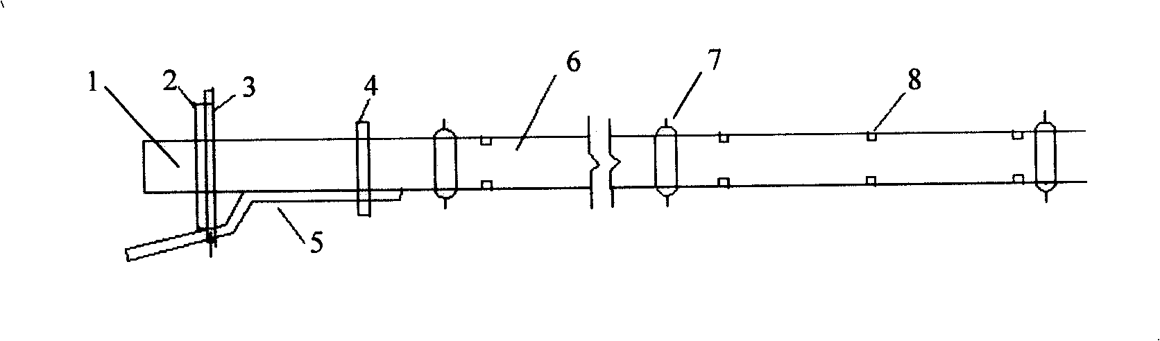
[0016] use The anchor pipe body (6) is made of ordinary straight seam welded pipe, the first row of grouting holes (8) is drilled from the hole bottom 20cm, the centering bracket (7) is welded at the bottom of the hole, and the grouting holes are drilled every 20 (8 ), and the centering bracket (7) is welded respectively on the upper section and the middle section of the anchor pipe body (6). Set a backing plate and nut (2) on the anchor head (1) as a prestressing device, set a stopper (4) at a distance of 800mm from the backing plate (3), and the lower part of the stopper is connected to the inlet of the grout return pipe (5). The grout return pipe outlet extends out of the anchor hole.

Embodiment 2

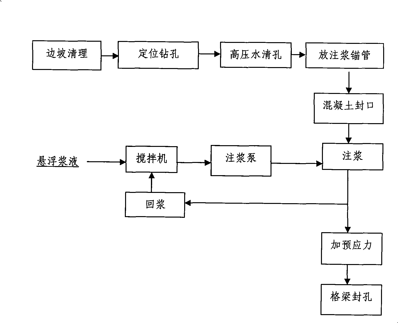
[0018] The left slope of an expressway section is a broken limestone slope with clay interlayer. The slope is 240m long and the maximum height is 39.6m, which is a forward slope. The slope is divided into four levels, each level of slope is 10m high, and the slope ratio is 1:0.75~1:1. The slope is cut by four groups of joints and several faults, and the groundwater of the natural slope at the top of the slope penetrates into the faults and fissures, causing the interlayer clay to soften and lose, and shallow rock strata to slip along the bed. The owner of the expressway requires ecological protection on the slope, no shotcrete, and shallow reinforcement of the slope. use image 3 The process flow shown implements cyclic grouting.

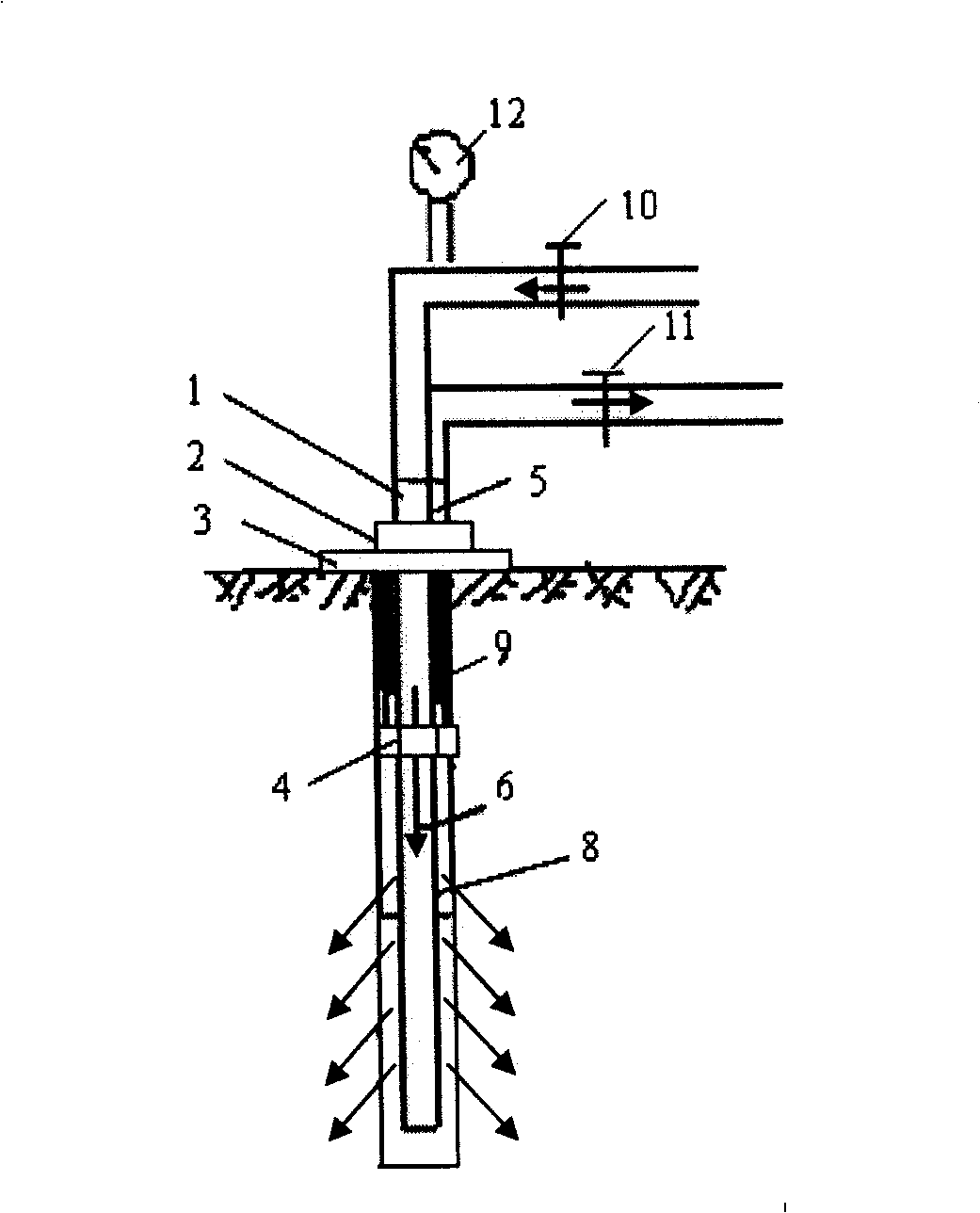
[0019] Such as figure 2 As shown, after cleaning the side slope, the anchor hole with a diameter of 54 mm and a depth of 4 to 6 m is drilled, and the anchor hole diameter is 100 mm larger than the outer diameter of the anchor pipe body (6). Cl...


PUM


Abstract

The invention discloses a weak-plane rock side slope grouting method and an anchor pipe for grouting. An anchor hole is drilled; the diameter of the anchor hole is more than the outside diameter of the anchor pipe body of at least 100 mm; the anchor pipe is placed in the anchor hole; concrete is filled in the anchor hole mouth; suspended grout in a double layer stirring mill is pressed to the anchor pipe for grouting by a grouting pump; when the grouting flow rate is more than the flow rate of grout absorption by rock or the grouting pressure is larger than the shearing resisting intensity of fissure filling in a shallow layer rock body, a grout returning valve is started in order that the grout in the hole returns to a grout storage barrel of the double layer stirring mill for circulating grouting. The weak-plane rock side slope grouting method and the anchor pipe for grouting effectively solve the difficult problems that the prior pressing in type grouting is easy to leak the grout, can not completely fill the fissure and can not be suitable for reinforcing the shallow layer. The circulating grouting method of the invention enlarges the grouting scope, improves the injection rate by the single hole, can effectively reinforce the water seepage and corrosion resisting capacity in the interlayer of the side slope and improve the stabilizing capacity of the whole side slope. The anchor pipe of the invention has the advantages of simple structure, easy manufacture and low costs.

Description

technical field [0001] The invention relates to a rock mass internal reinforcement method and a device used in geotechnical engineering, in particular to a grouting reinforcement method and a grouting device used for rock slopes with weak interlayers. Background technique [0002] In geotechnical engineering, rocky slopes with weak interlayers are prone to landslides under the action of rainfall and groundwater. At present, in order to prevent shallow landslides caused by water erosion piping on weak interlayer rock slopes, there are mainly two reinforcement methods used: one is the combined method of bolt reinforcement rock formation and shotcrete sealing slope surface; the other It is used for high-pressure grouting in rock formations to fill karst caves, faults, weak interlayers and joint fissures. [0003] There are serious shortcomings in the joint reinforcement method of anchor bolt and spray mix: the temperature difference between the atmosphere and the rock layer ca...

Claims


Application Information

Patent Timeline
Patent Type & Authority Applications(China)
IPC IPC(8): E02D17/20E21D20/02E21D21/00E02D5/74
Inventor 胡毅夫陈沅江陈明宪谢立新
Owner CENT SOUTH UNIV
Why Eureka
Try Eureka