Gravure platemaking roll and its manufacturing method

A technology of gravure plate making and manufacturing method, applied in the directions of printing plate, printing plate preparation, ion implantation and plating, etc., can solve the problems of poor lubricity, deterioration, unsharp cutting of the squeegee, etc. Excellent strength, the effect of omitting the chrome plating process

Inactive Publication Date: 2008-09-24
THINK LABORATORY CO LTD
View PDF8 Cites 9 Cited by
  • Summary
  • Abstract
  • Description
  • Claims
  • Application Information

AI Technical Summary

Problems solved by technology

When there is a large amount of ink that causes fog in the non-drawing part of the printing plate, the reason is that the squeegee becomes less sharp and the ink cutting becomes poor, or the reason is that the printing plate is too mirror-like and self-lubricating. Poor performance, resulting in direct contact between the doctor blade and the roller surface, the doctor blade vibrates slightly to allow the ink to pass through

Method used


Image

  • Gravure platemaking roll and its manufacturing method
  • Gravure platemaking roll and its manufacturing method
  • Gravure platemaking roll and its manufacturing method

Examples


Embodiment 1

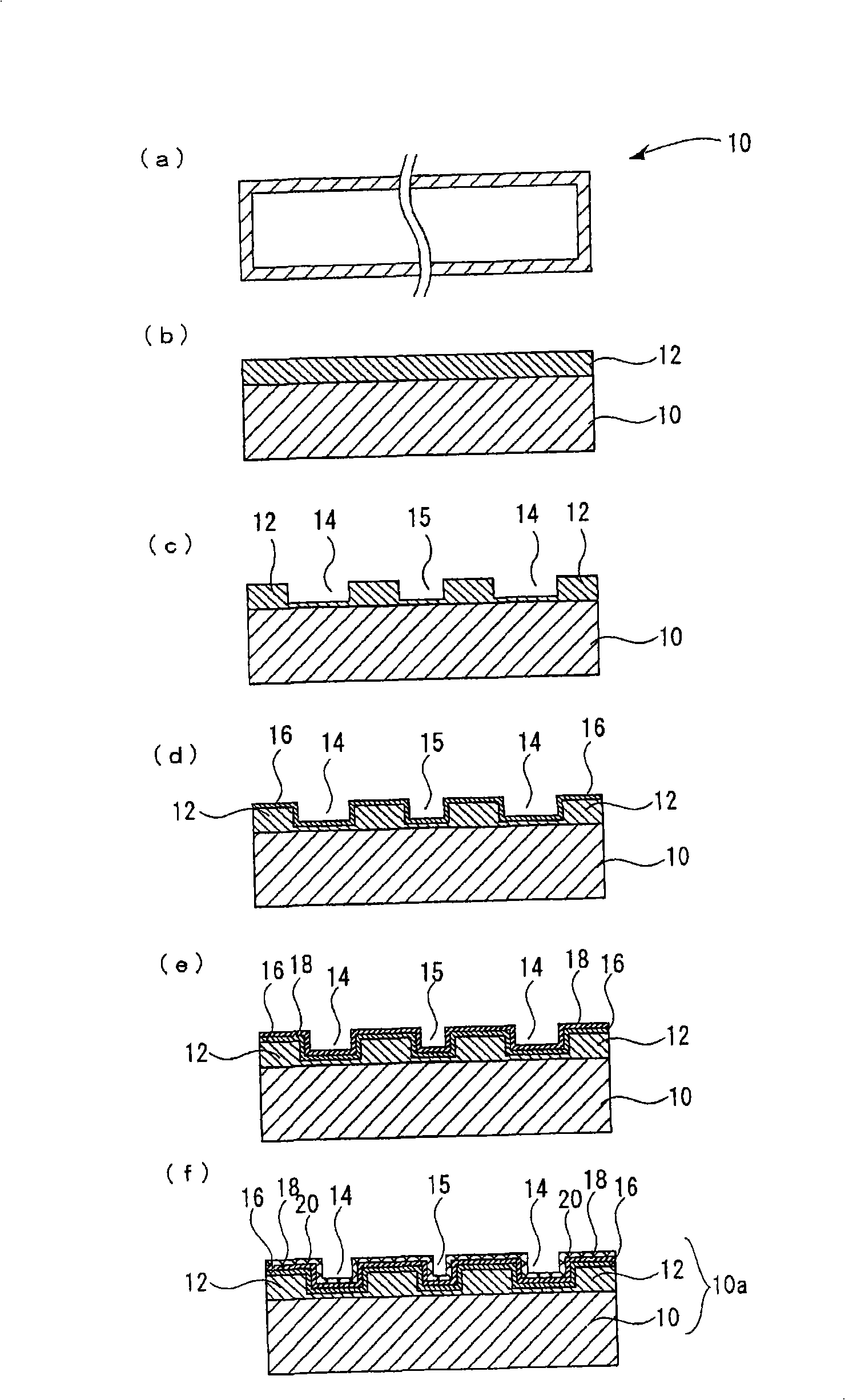
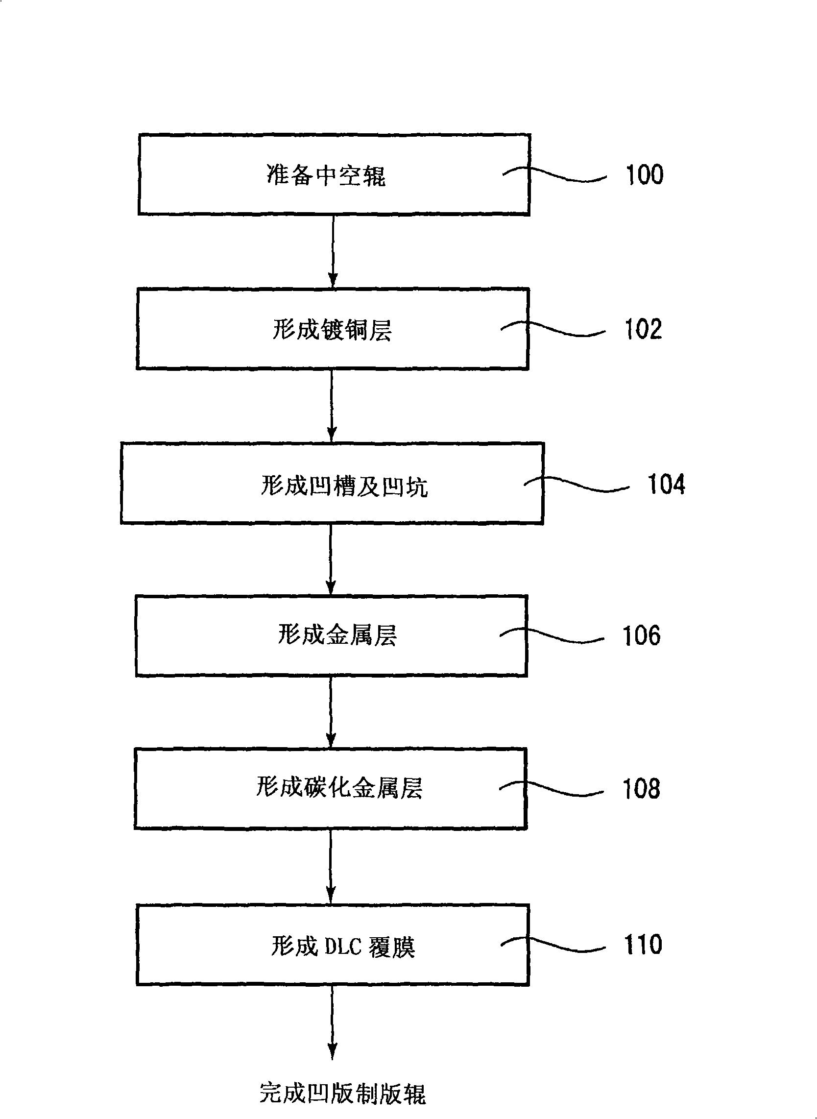
[0062] Install a gravure cylinder (aluminum hollow roll) with a circumference of 600 mm and a surface length of 1100 mm in the plating tank, and use an automatic sliding device based on a computer system to move the anode chamber to the hollow roll to a distance of 20 mm, so that the plating solution overflows and submerges the hollow roll. / dm2, 6.0V to form a copper plating layer of 80μm. The plating time was 20 minutes, no peeling etc. occurred on the plating surface, and a uniform copper plating layer was obtained.

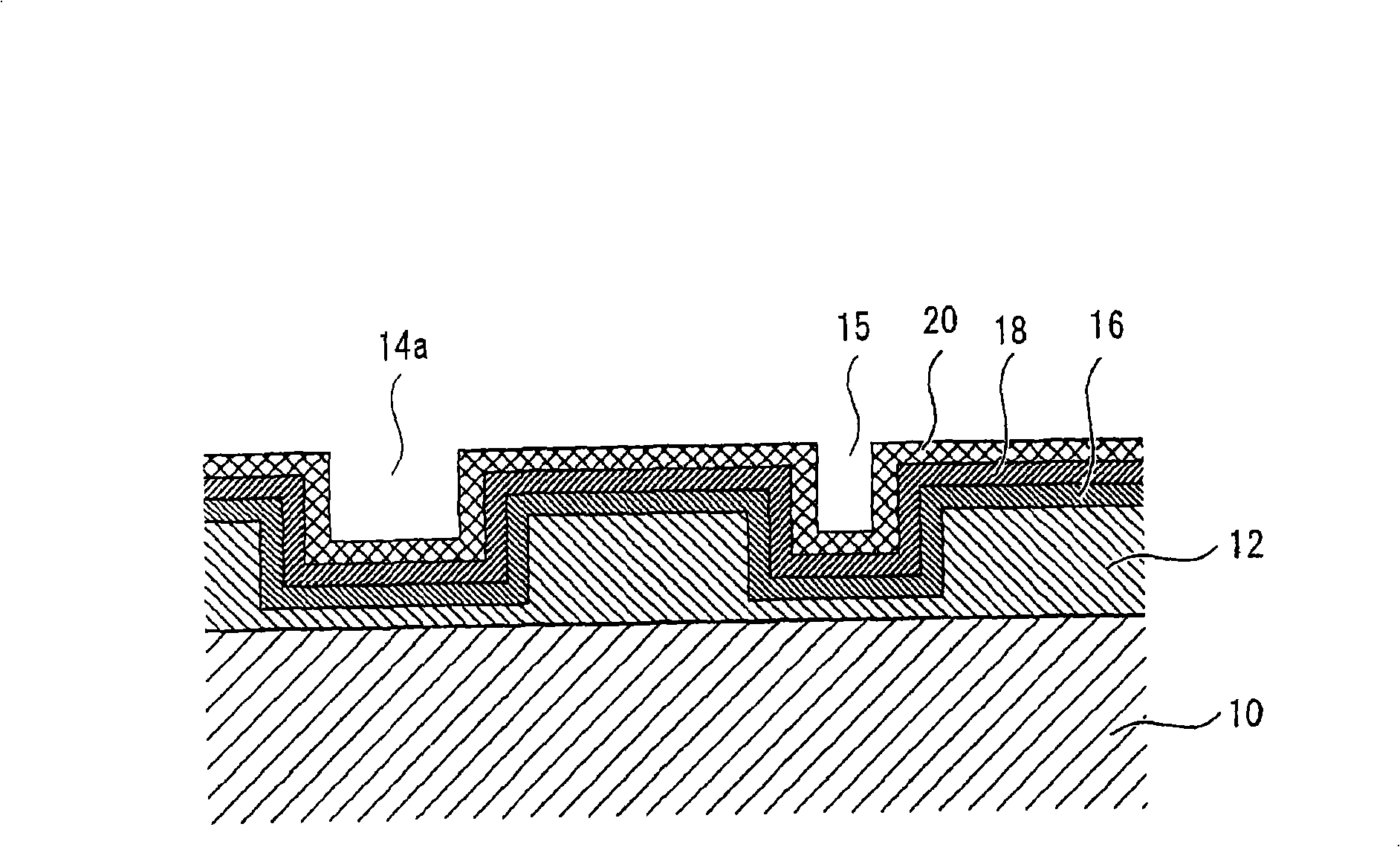
[0063] A photosensitive film is applied on the copper plating layer formed above, and the image is subjected to laser exposure, development, patterning, and a resist image is formed, followed by dry etching such as plasma etching, and the image composed of grooves is engraved and formed. pits, after which the resist image is removed to produce a hollow roll forming a printing plate.

[0064] A tungsten (W) layer was formed by sputtering on the copper plating ...

Embodiment 2

[0069]In the same manner as in Example 1, a hollow roll in which grooves and pits were formed was produced. For the above-mentioned hollow roll, except that the tungsten (W) sample was changed to a silicon (Si) sample, the gravure plate-making roll was processed in the same way as in Example 1, and after the printing test was similarly performed, it was obtained in the same way as in Example 1. A printed matter that does not generate fog in a part with slight scratches, or a part in which fine scratches are not applied with sandpaper also rarely generates fog and has good indexability. In these examples, it was confirmed that the diamond-like carbon (DLC) coating also has performance comparable to that of the conventional chromium layer and can be used as a substitute for the chromium layer sufficiently.

[0070] It was also confirmed that similar tests were performed using titanium (Ti) and chromium (Cr) as metal samples, and similar results were obtained.

Embodiment 3

[0072] A level of 0% to 100% is prepared as the board information before the board is formed. And, make the pattern that 2 laser beams are irradiated side by side along the roll peripheral direction, so that the unit exposure area as 3.5 μ m * 7.0 μ m is formed in the arrangement along the longitudinal direction of the roll surface with a pitch of 140 μ m, and the pitch in the roll peripheral direction is Randomly arrange within the range of 70 μm to 140 μm, and create digital version information in which the digital information of the screen screen screened through the screening program is superimposed on the above-mentioned grade.

[0073] Next, apply a positive-type photosensitive film made by Canada Creosity Technology Co., Ltd. on the mirror-finished copper-plated surface of the roller, so that the residual solvent is 2% or less, and then dry the photosensitive film, and then use the equipment that can be used at 1.8 The size of μm×7.0μm is used as a unit to output a lase...


PUM

PropertyMeasurementUnit
thicknessaaaaaaaaaa
depthaaaaaaaaaa
thicknessaaaaaaaaaa

Abstract

A novel photogravure engraving roll capable of improving plate fog, being provided with a surface reinforcing film layer completely free from toxicity and the possibility of pollution, and being excellent in plate wear; and a production method of the roll. The photogravure engraving roll comprises a metal hollow roll, a copper-plated layer provided on the surface of the hollow roll and formed with many gravure cells on the surface thereof, a metal layer provided on the surface of the copper-plated layer, a metal carbide gradient layer of the metal provided on the surface of the metal layer, and a diamond-like carbon film covering the surface of the metal carbide gradient layer, wherein a pit being smaller than the minimum gravure cell in the highlighted portion of the copper-plated layer and having a size not permitting ink transfer is arranged so that at least one pit exists in the one-pitch area of a screen line in a non-printing image.

Description

technical field [0001] The present invention relates to a gravure plate-making roll and a manufacturing method thereof capable of improving fog and capable of preparing a surface-strengthening coating layer having sufficient strength without using chrome plating, and particularly relates to a surface-strengthening method as a substitute for a chrome layer A gravure plate-making roll provided with a diamond-like carbon (DLC) layer as a covering layer and a manufacturing method thereof. Background technique [0002] In gravure printing, microscopic recesses (grooves) corresponding to plate-making information are formed on a gravure plate-making roll (gravure cylinder) to form a plate, and ink is filled in the grooves and transferred to the printed material. In ordinary gravure rolls, a hollow roll made of metal such as aluminum or iron or reinforced resin such as carbon fiber reinforced resin (CFRP) is provided with a copper-plated layer (plate material) for plate formation. ...

Claims


Application Information

Patent Timeline
Patent Type & Authority Applications(China)
IPC IPC(8): B41C1/02B41N1/20B41N1/22C23C14/06C23C28/00
CPCC23C28/343C23C28/322C23C28/36C23C16/029B41N1/20B41N1/22C23C16/26C23C28/341B41C1/05C23C28/347B41C1/02C23C14/06
Inventor 重田龙男佐藤勉杉山浩一浅野贵之
Owner THINK LABORATORY CO LTD
Why Eureka
Try Eureka