Multimode autofluorescence tomography molecule image instrument and rebuilding method

An autofluorescence and molecular imaging technology, which is used in radiological diagnosis instruments, instruments, inoculation and ovulation diagnosis, etc., can solve the problems of sensitivity, the deviation of the position accuracy and intensity accuracy of the reconstructed light source, and the large number of points in the solution area. The effect of improving the signal-to-noise ratio

Active Publication Date: 2008-11-12
INST OF AUTOMATION CHINESE ACAD OF SCI
View PDF0 Cites 47 Cited by
  • Summary
  • Abstract
  • Description
  • Claims
  • Application Information

AI Technical Summary

Problems solved by technology

[0003] Due to the strong scattering characteristics of the reconstructed target area, photons undergo a large amount of scattering during the internal transmission process, thus deviating from the original straight-line transmission track; the amount of boundary data measured at the boundary of the reconstructed target area by optical detection instruments is limited, and the requirements The number of points in the solution area is very large, so autofluorescence tomography is an ill-posed problem, which is very ill-conditioned, and its solution is not unique and is very sensitive to measurement errors and noise
At the same time, the reconstruction target area is a complex heterogeneous area. If the reconstruction target area is assumed to be a homogeneous area, the obtained reconstruction light source will have a large deviation in position accuracy and intensity accuracy.

Method used


Image

  • Multimode autofluorescence tomography molecule image instrument and rebuilding method
  • Multimode autofluorescence tomography molecule image instrument and rebuilding method
  • Multimode autofluorescence tomography molecule image instrument and rebuilding method

Examples


Embodiment Construction

[0038] The reconstruction method of the present invention will be described in detail below in conjunction with the accompanying drawings. It should be noted that the described embodiments are only intended to facilitate the understanding of the present invention, and have no limiting effect on it.

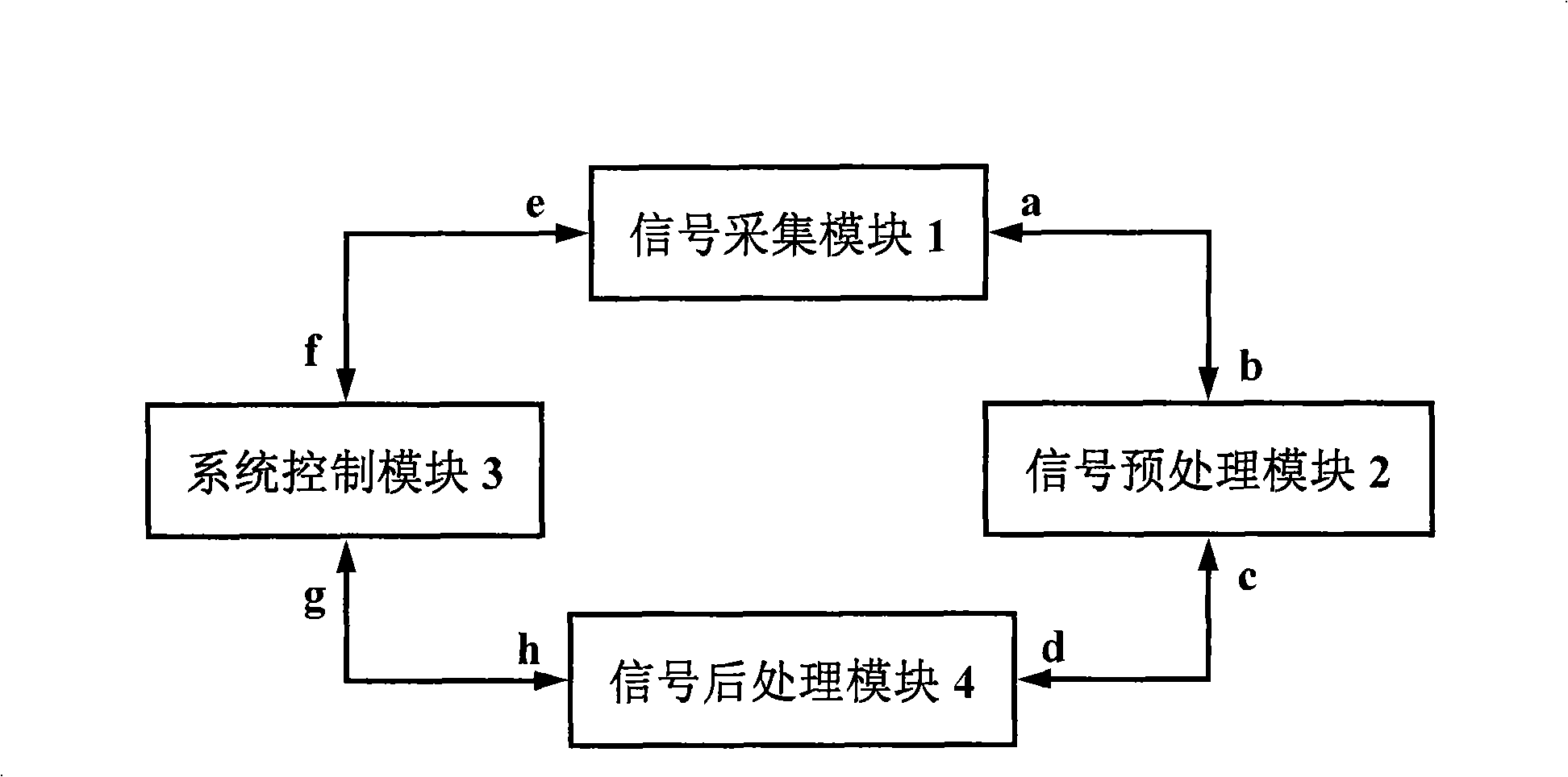
[0039] According to attached figure 1 As mentioned in the overall structure of the multimodal autofluorescence tomography molecular imaging instrument, the multimodal autofluorescence tomography molecular imaging instrument involved in the present invention mainly includes four parts, which are signal acquisition module 1, signal preprocessing module 2, and system control module. module 3 and signal post-processing module 4, the modules in the instrument are connected together through a data bus or a control bus. The signal acquisition module 1 has a first data port a and a first control port e; the signal preprocessing module 2 has a second data port b and a third data port c, an...


PUM


Abstract

The invention discloses a multi-modality autofluorescence molecular tomographic imaging instrument, comprising a signal gathering module, a signal preprocessing module, a system control module, and a signal post-processing module. The method of the invention comprises determining the feasible region of light source through X-ray imaging and autofluorescence tomographic imaging based on multi-stage adaptive finite element combined with digital mouse, reconstruction target area optical characteristic parameter, and modality fusion, and adaptive optimized factorization for partial texture according to the posterior error estimation to obtain the fluorescence light source in reconstruction target area. The morbidity problem of autofluorescence molecular tomographic image can be efficiently solved, and the precise reconstruction of the autofluorescence light source can be carried out in the complicated reconstruction target area by the multi-modality fusion imaging mode of the autofluorescence molecular tomographic imaging. The precise reconstruction of the autofluorescence light source can be finished by the liquid nitrogen cooling CCD probe, multi-angle fluorescence probe technology, and multi-modality fusion technology, and the autofluorescence molecular tomographic imaging algorithm based on multi-stage adaptive finite element with the non-uniformity characteristics of the reconstruction target area.

Description

technical field [0001] The invention belongs to the field of molecular imaging, and relates to an in-body fluorescence tomography imaging instrument, in particular to a multi-mode autofluorescence tomography molecular imaging instrument. Background technique [0002] Autofluorescence tomography is an emerging optical molecular imaging technology in recent years. Autofluorescence uses luciferase to mark the reconstruction target. In the presence of ATP and oxygen, if luciferase encounters the substrate luciferin, luciferase It will catalyze the oxidation reaction of fluorescein and generate photons, the intensity of which is proportional to the number of labeled targets. Outside the reconstruction target area, the photons escaping from the reconstruction target area can be detected directly by using high-sensitivity optical detection instruments, and then the position and intensity of the fluorescent light source inside the reconstruction target area can be obtained by using ...

Claims


Application Information

Patent Timeline
Patent Type & Authority Applications(China)
IPC IPC(8): A61B5/00A61B6/00A61B10/00G06T5/00
Inventor 田捷秦承虎吕玉杰杨鑫
Owner INST OF AUTOMATION CHINESE ACAD OF SCI
Why Eureka
Try Eureka