Technological system and method for removing carbon, nitrogen and sulphur in waste water synchronously

A waste water and removal technology, applied in separation methods, sulfur preparation/purification, chemical instruments and methods, etc., can solve the problems of not being able to remove carbon, nitrogen and sulfur at the same time, the complex process of carbon, nitrogen and sulfur, and the difficulty of separating elemental sulfur, etc. Small footprint, easy operation, no secondary pollution

Active Publication Date: 2008-11-12
HARBIN INST OF TECH +1
View PDF3 Cites 25 Cited by
  • Summary
  • Abstract
  • Description
  • Claims
  • Application Information

AI Technical Summary

Problems solved by technology

[0004] The purpose of the present invention is to solve the shortcomings of the existing technology for removing carbon, nitrogen and sulfur in wastewater, which are complex, high operating costs, low treatment efficiency, and difficult to separate elemental sulfur

Method used


Image

  • Technological system and method for removing carbon, nitrogen and sulphur in waste water synchronously

Examples


specific Embodiment approach 1

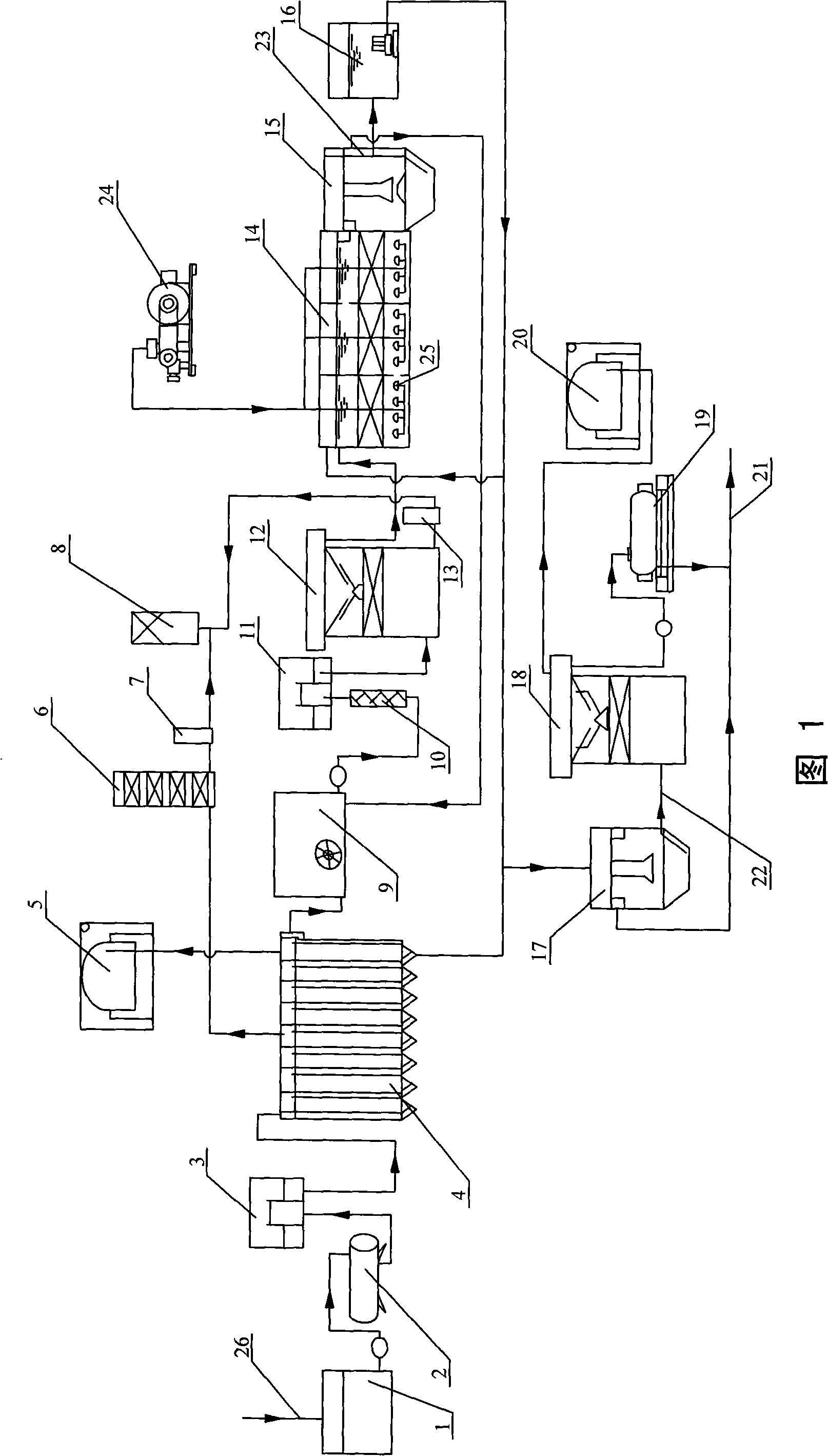
[0010] Specific embodiment 1: illustrate in conjunction with Fig. 1, the process system of synchronously removing carbon, nitrogen and sulfur in wastewater in this embodiment is composed of regulating tank 1, first heat exchanger 2, first lifting well 3, sulfate reduction and organic matter Removal device 4, first biogas storage tank 5, biological deodorization tower 6, first elemental sulfur separation device 7, elemental sulfur recovery device 8, mixing tank 9, second heat exchanger 10, second lifting well 11, carbon nitrogen sulfur Synchronous removal device 12, second elemental sulfur separation device 13, nitrification reactor 14, sedimentation tank 15, mud collection well 16, concentration tank 17, anaerobic sludge nitrification device 18, sludge centrifugation device 19, second biogas storage Tank 20, discharge pipe 21, connecting pipe 22, siphon pipe 23, blower 24, aeration head 25 and water inlet pipe 26 are formed; The water inlet at the top of the first heat exchang...

specific Embodiment approach 2

[0012]Specific embodiment two: the difference between this embodiment and specific embodiment one is that the sulfate reduction and organic matter removal device 4 is the integration described in the patent No. ZL 00206243.7 (its announcement number is CN2420272, and the announcement date is 2001.02.21) Two-phase anaerobic biological treatment reactor or anaerobic baffled reactor. Others are the same as in the first embodiment.

specific Embodiment approach 3

[0013] Specific embodiment three: the difference between this embodiment and specific embodiment one is that the carbon, nitrogen and sulfur synchronous removal device 12 is the reaction described in Chinese Patent Application No. 200710072195.0 (its publication number is CN101050031, and the disclosure date is 2007.10.10) reactor or granular sludge expanded bed reactor.


PUM


Abstract

The invention provides a process system and a method for synchronously removing carbon, nitrogen and sulfur in wastewater, relating to a device and a method for treating the wastewater. The process system solves the defects of complicated process, high operating cost, low processing efficiency and difficult elemental sulfur separation in the prior art for removing the carbon, the nitrogen and the sulfur in the wastewater. In the process system, an outlet of a carbon-nitrogen-sulfur synchronous removal device is communicated with an inlet of a nitrifying reactor; and an outlet of the nitrifying reactor is communicated with an inlet of a sedimentation tank. The method comprises the following steps of: transforming organic substances, sulfate and ammonia nitrogen in the wastewater into carbon dioxide, elemental sulfur and nitrogen respectively; transforming H2S and NH3 metabolized in gas phase into the elemental sulfur and the nitrogen; and degrading sludge generated in the growth of microorganisms. The method has the advantages of high processing efficiency, no secondary pollution, simple process, low operating cost, completely recycled elemental sulfur and so on; and the process system also has the advantages of occupied area conservation and convenient operation.

Description

technical field [0001] The invention relates to a wastewater treatment device and method, in particular to a process system and method for treating carbon, nitrogen and sulfur-containing wastewater. Background technique [0002] With the rapid development of industries such as fermentation, pharmaceuticals, and food processing, a large amount of organic wastewater containing sulfur and nitrogen is discharged into receiving water bodies. Nitrogen-containing compounds (such as ammonia nitrogen) can accelerate the proliferation of algae and other aquatic organisms, trigger eutrophication of water bodies, and cause algal blooms and red tides. Sulfur-containing compounds (such as sulfate) can be reduced to sulfide by microorganisms under anaerobic conditions, which not only causes biological corrosion, but also produces toxic and harmful hydrogen sulfide gas, which brings great harm to people's production and life. Therefore, it is very necessary and urgent to develop efficient ...

Claims


Application Information

Patent Timeline
IPC IPC(8): C02F9/14C02F1/70C02F3/30B01D53/52C01B17/02
Inventor 王爱杰刘春爽任南琪韩洪军毕建培陈川邓旭亮
Owner HARBIN INST OF TECH
Why Eureka
Try Eureka