
Process for producing sintered ore

A production method and technology for sintered ore, which are applied in the field of sintered ore production for blast furnaces, can solve the problems of no particle drying, collapse of sintered raw material particles, no drying, etc., and achieve the effects of improving ventilation resistance and reducing the amount of carbon material.

Inactive Publication Date: 2008-11-19
JFE STEEL CORP
View PDF11 Cites 7 Cited by
  • Summary
  • Abstract
  • Description
  • Claims
  • Application Information

AI Technical Summary

Problems solved by technology

On the other hand, in order to shorten the drying time, it is necessary to increase the temperature of the gas, but if the temperature is raised above 150°C, there is a problem that the belt will cause thermal elongation and S-shape swing
[0015] In addition, in the method described in Patent Document 2, which blows hot air into the buffer hopper to dry the stored sintering raw material particles, there is a problem that, similar to the above, although the drying of the part contacting with the hot air is carried out, it is not carried out. Drying of the part in contact with hot air, for example, even if the side wall of the buffer hopper is heated, only the part in contact with the side wall is dried, and the particles passing through the part away from the side wall are not dried
If the sintering raw material particles in such a non-uniform dry state are loaded on the pallet of the sintering machine and sintered, there are problems such as uneven sintering, which affects the yield and productivity.
[0016] In addition, in the method described in Patent Document 3 in which the granulated sintered raw material particles are loaded onto the trolley and then dried by supplying hot air from above the loaded layer, since the sintered raw material particles are dried in a static state, although It can prevent particles from collapsing during drying, but it will increase in size due to blowing hot air, and requires a huge investment in equipment
[0017] In the method described in Patent Document 4, in which hot air is fed from the discharge port side of the granulation process to dry, the granulated sintering raw material particles tend to collapse, which leads to insufficient drying, and normal sintering machine operations cannot be performed. The problem
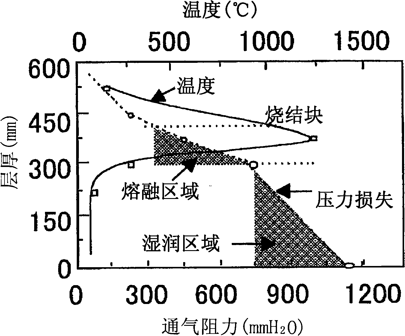
[0018] In other words, these conventional proposals were developed for the purpose of drying the granulated sintered raw material and reducing the influence of the wet area, and no practical technology has been established yet.

Method used


Image

  • Process for producing sintered ore
  • Process for producing sintered ore
  • Process for producing sintered ore

Examples


Embodiment 1、2、3

[0157] Invention examples 1 to 3 are application examples suitable for the process of the present invention shown in FIG. 4 . This method is an example of the following: First, between the mixing tumbler mixer 2a and the granulation tumbler mixer 2b, adding characteristics of maintaining granulation strength) and an organic binder having a carboxylic acid group are granulated, and then dried using a rotary kiln 3 for drying. In the above example, the organic binder is added to the mixed sintered raw material particles at the inlet side of the drum mixer (primary mixer) 2b for granulation. Immediately thereafter, in the drum mixer (secondary mixer) 2b for granulation, pseudo particles are formed by the main action of the above-mentioned organic binder, and the pseudo particles are supplied to the rotary kiln 3 for drying.

[0158] The heating medium for drying blown into the furnace from the outlet side of the drying rotary kiln 3 utilizes the exhaust gas supplied from the win...

Embodiment 2

[0163] Under various conditions shown in Table 5, the sintering raw materials were granulated and dried to conduct a sintering experiment. The effect is good when there is no return ore, and the sintering time is also shortened.

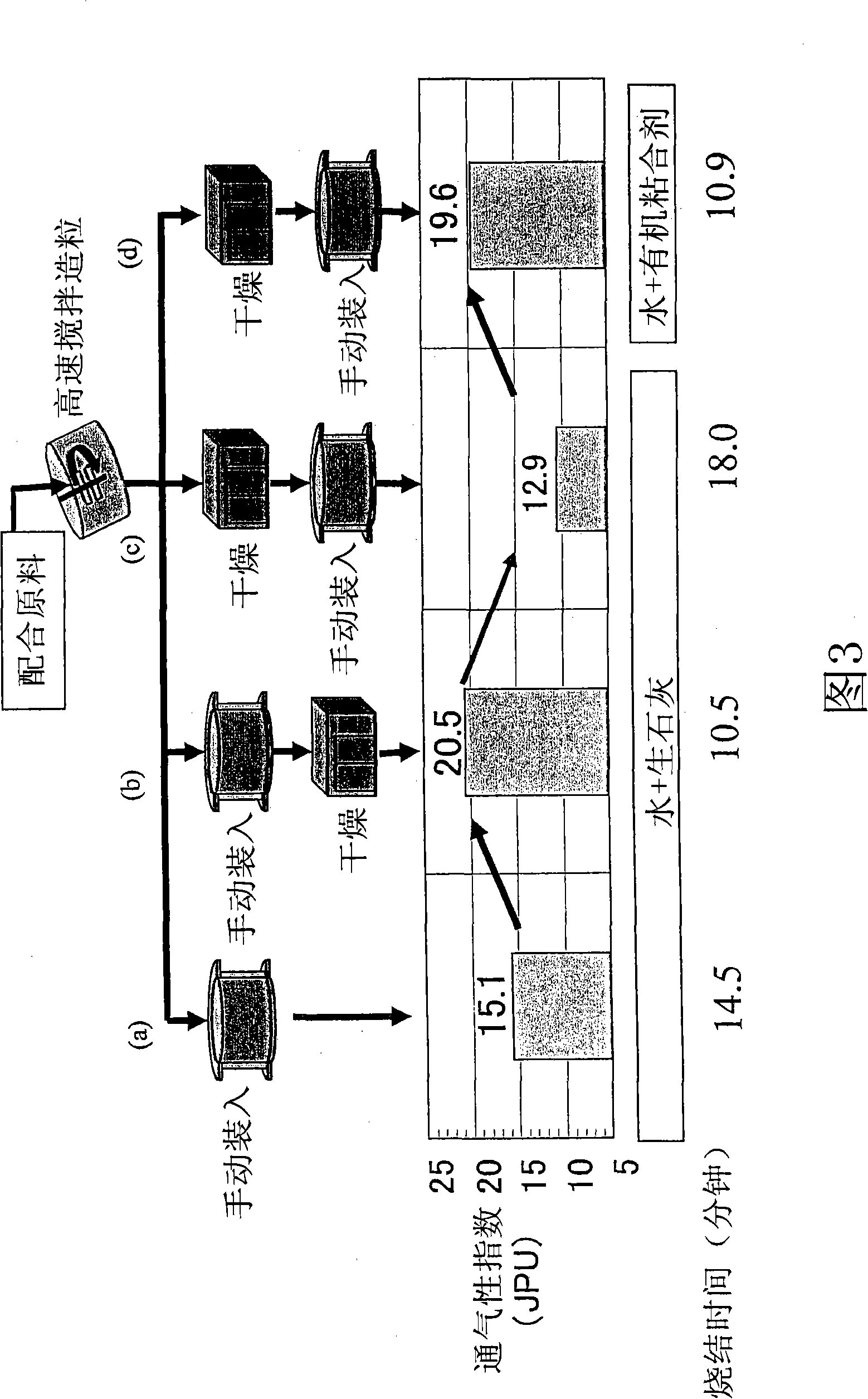
[0164] Fig. 16 shows the following: comparison of the general process A in which water and quicklime are added as binders to the sintered raw materials through a drum mixer without drying and sintered, and the process B in which gum arabic is added in a powder state instead of the quicklime in the above-mentioned general process A As well as process C in which gum arabic is added as an aqueous solution, the effect of the addition method of the organic binder on the sinterability is compared. From this result, it can be seen that the organic binder is preferably directly added in a powder state.

[0165] In addition, FIG. 17 shows the following: In the case of using an organic binder (gum arabic), in order to further observe the influence on the sint...

Embodiment 3

[0169] Under various conditions shown in Table 6, the sintered raw materials were granulated and dried, and the sintering experiment was carried out with a real machine to measure the air volume, sintering time and productivity during sintering, and record the results in Table 6 together. The sintering experiment was carried out under the respective conditions at two levels when the layer thickness was set as the standard 600mm and when it was raised to 900mm. In the sintering machine operation of 600mm, the carbon material was 5.5mass% as a benchmark, and the sintering at 900mm In machine operation, due to the increase of layer thickness, 4.0mass% of carbon material is used as a benchmark.

[0170] Comparative Example 1 is an example using a conventional inorganic binder. The sintering time in the sintering machine operation is 30 minutes when the layer thickness is 600 mm, and the time is only extended by 45 minutes when the layer thickness is 900 mm. .

[0171] On the othe...


PUM

PropertyMeasurementUnit
Thicknessaaaaaaaaaa

Abstract

A process for sintered-ore production which comprises a granulation step, a drying step, and a sintering step. The granulation step comprises adding water and a binder to a raw material to be sintered which contains a carbonaceous material and granulating the mixture to produce raw granules to be sintered. The drying step comprises drying the raw granules to be sintered to thereby produce dried raw granules to be sintered which have a water content of 4.0 mass% or lower. The sintering step comprises introducing the dried raw granules into a sintering apparatus and sintering the granules.

Description

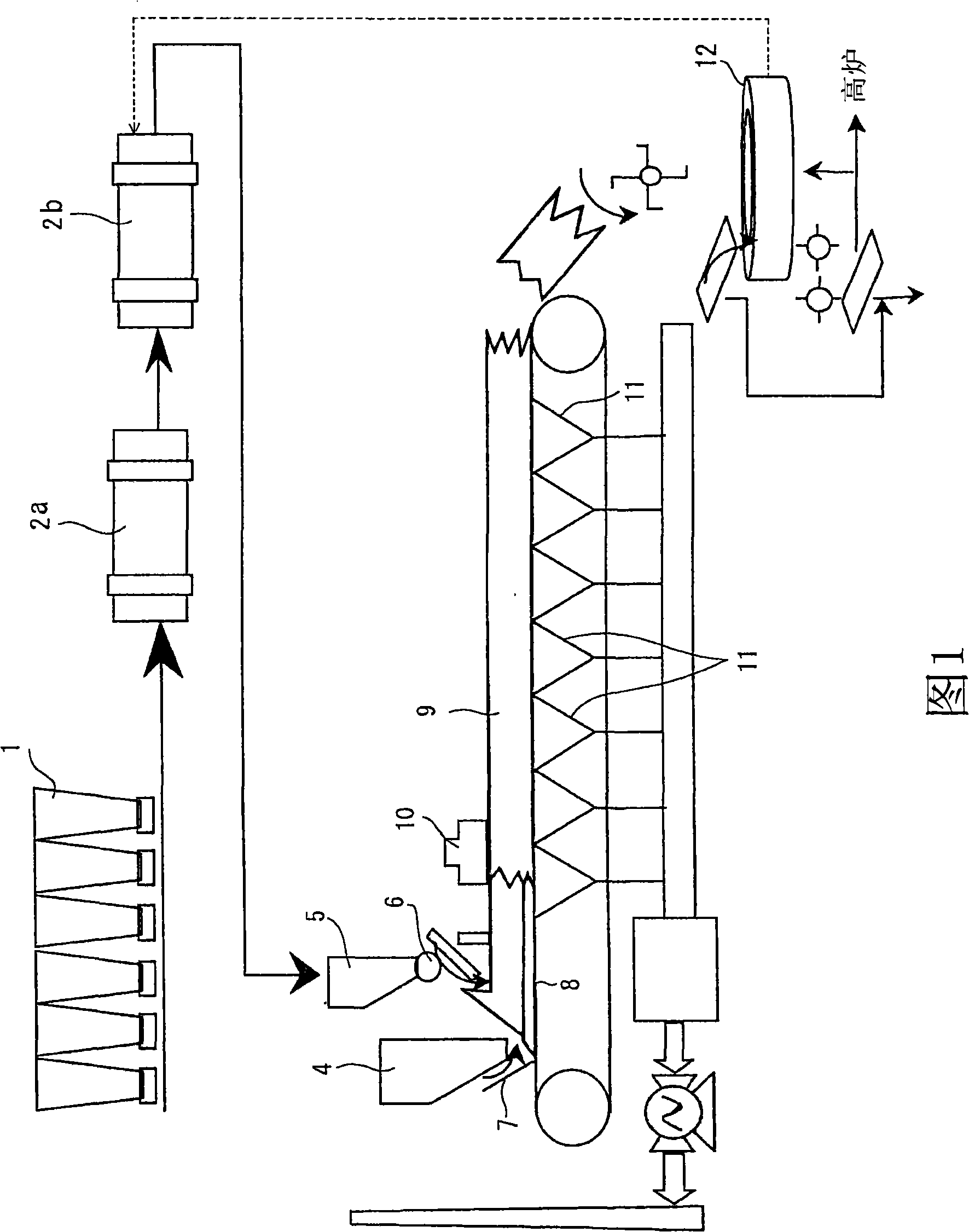
technical field [0001] The present invention relates to a method for producing sintered ore for blast furnaces. In particular it concerns the moisture content of the pelletized sintering raw material and the formation of wet areas during sintering. Background technique [0002] Sintered ore, which is used as the main raw material in blast furnace ironmaking, is manufactured through the process shown in Figure 1. Iron ore powder whose sintering raw material is less than 10mm and with an average particle size of about 1.0-5.0mm, recycled powder in ironworks, sintered ore under-sieve powder, limestone, dolomite and other CaO-containing raw materials, quicklime and other granulation aids, and coke powder, anthracite and other coagulation materials, etc. CaO-containing raw materials such as limestone and dolomite are hereinafter referred to as CaO-based auxiliary materials. The raw materials for sintering are stored in the hopper 1 . The above-mentioned raw materials are cut ...

Claims


Application Information

Patent Timeline
IPC IPC(8): C22B1/20C22B1/16
CPCC22B1/205C22B1/20C22B1/24
Inventor 大山伸幸佐藤秀明
Owner JFE STEEL CORP
Learn More