
Oxygen bottom blowing continuous copper smelting apparatus

A technology of oxygen bottom blowing and copper smelting device, applied in rotary drum furnace, crucible furnace, furnace and other directions, can solve the problems of not being widely promoted, depletion, complicated process and so on

Inactive Publication Date: 2008-12-24
CHINA ENFI ENGINEERING CORPORATION
View PDF1 Cites 33 Cited by
  • Summary
  • Abstract
  • Description
  • Claims
  • Application Information

AI Technical Summary

Problems solved by technology

[0007] Although the above two continuous copper smelting processes have solved the environmental protection problems of blowing operations, they still have some shortcomings and need to be further improved:
[0008] The Mitsubishi method consists of four furnaces (smelting furnace, depleted electric furnace, blowing furnace, anode furnace) self-flowing configuration. The melting furnace of the first process needs to be arranged on a higher floor, and the construction cost is relatively high. In addition, the Mitsubishi method’s The slag is diluted by an electric furnace, and the copper content in the waste slag reaches 0.6-0.7%, which is much higher than the average grade of ore mined by most large-scale copper mines in my country, and the resources have not been fully utilized
[0009] The disadvantage of flash furnace continuous blowing is that the copper matte needs to be crushed first, then dried and ground before it can be blown. The process is complicated, and it is difficult to guarantee a 100% recovery rate in each process. mechanical loss
In addition, the liquid high-temperature copper matte is crushed, and its physical heat is almost completely lost. The process of water crushing and solid copper matte, drying and blowing requires an external heat source, and the use of heat energy is unreasonable.
Copper matte crushing requires a large amount of water to wash, plus drying and crushing, additional labor and power consumption, resulting in increased blowing costs, which may be an important reason why this process has not been widely promoted over the years
[0010] In addition, there is also the Noranda continuous blowing method, which is still in the stage of industrial testing.

Method used


Image

  • Oxygen bottom blowing continuous copper smelting apparatus
  • Oxygen bottom blowing continuous copper smelting apparatus

Examples


Embodiment 1

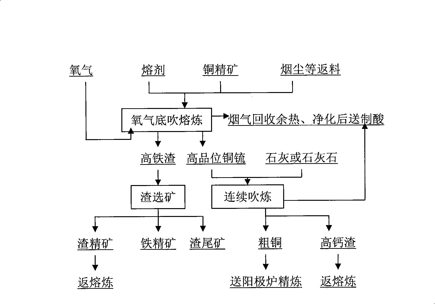
[0092] A technique for continuous copper smelting by oxygen bottom blowing is characterized in that the technique comprises the following steps:

[0093] (1) Copper sulfide concentrate and flux, returned intermediate copper materials including dust, slag copper concentrate, blowing furnace slag, etc., are mixed and granulated by a disc granulator, and sent to the bottom blowing smelting furnace by a belt feeder The upper part of the furnace feed port is fed into the furnace, and oxygen is sent into the furnace through the oxygen spray gun installed at the bottom of the furnace at an angle of 0° to the vertical line for smelting reaction. The temperature is 1080°C;

[0094] (2) The copper matte generated by the bottom-blowing smelting furnace is discharged to the chute connected with the bottom-blowing smelting furnace through the siphon discharge port at one end of the bottom-blowing smelting furnace; the copper matte is sent to the end of the bottom-blowing smelting furnace t...

Embodiment 2

[0100] Oxygen is fed into the furnace through the oxygen lance installed at the bottom of the furnace at an angle of 16° to the vertical for smelting reaction, and oxygen is fed through the oxygen lance installed at the bottom of the bottom blowing furnace at an angle of 16° to the vertical for blowing The mixed pellets are smelted to produce copper matte and smelting slag. The melting temperature is 1100°C and the blowing temperature is 1250°C. Except for the high-temperature flue gas, the others are the same as those described in Example 1.

Embodiment 3

[0102] A process for continuous copper smelting using oxygen bottom blowing, characterized in that:

[0103] Copper matte converting refers to: the liquid high-temperature copper matte produced from the bottom-blown smelting furnace is continuously injected into the bottom-blown converting furnace with oxygen through the chute, and oxygen-enriched air is continuously fed from the bottom of the converting furnace to continuously blow high-grade copper matte ;

[0104] At the same time, the furnace top is not opened, and the flux lime powder is sent into the furnace with oxygen through the silo and metering belt feeder according to the calculation requirements to make slag from the oxygen lance; One end has a hole at the upper part to discharge smelting slag, and a hole at the lower part to set up a siphon device to discharge blister copper to realize continuous addition of copper matte, continuous blowing, continuous addition of flux, continuous slagging, continuous slag discha...


PUM

PropertyMeasurementUnit
thicknessaaaaaaaaaa
thicknessaaaaaaaaaa
thicknessaaaaaaaaaa

Abstract

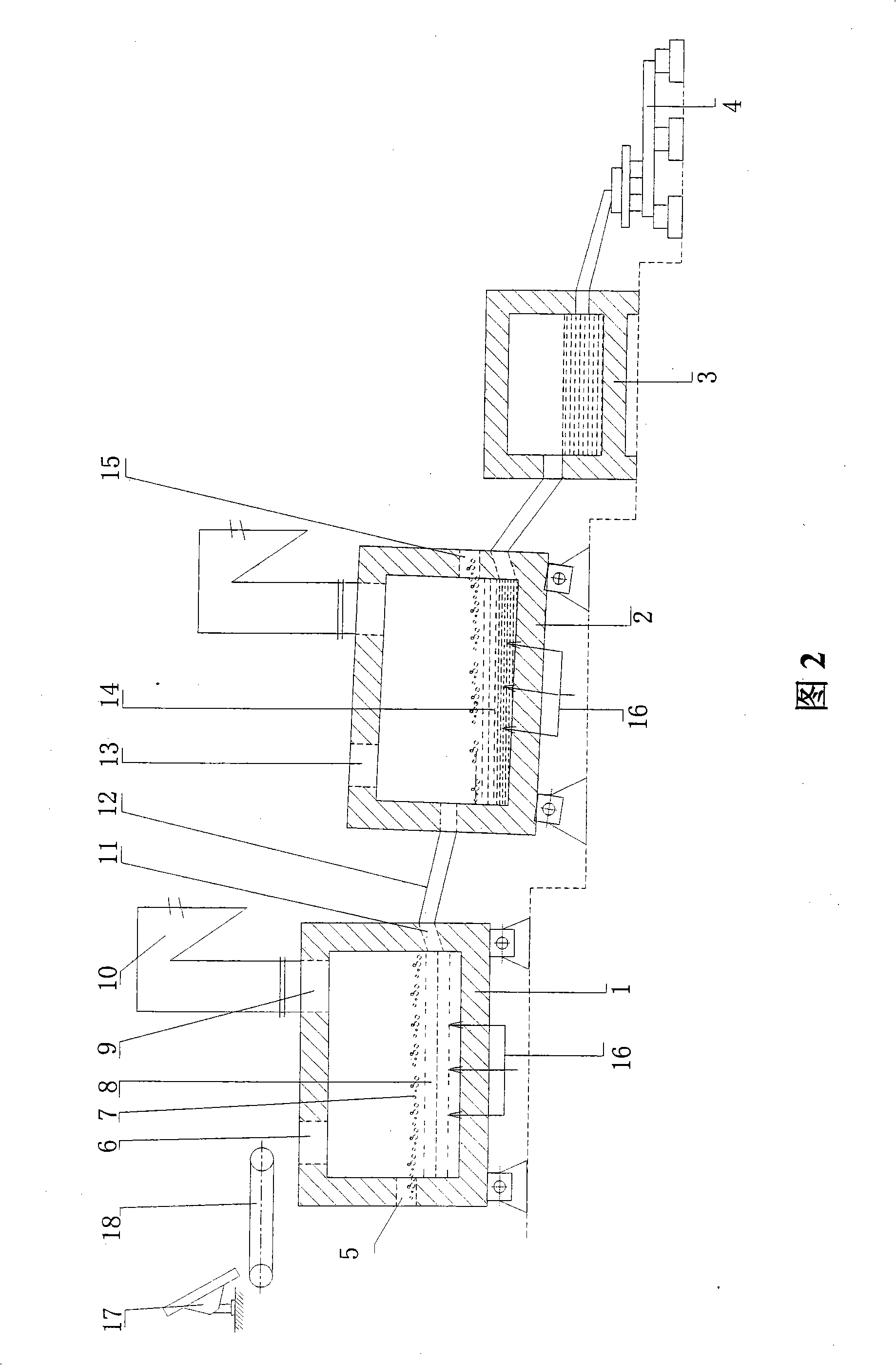
The invention provides an oxygen bottom blowing continual copper smelting device used in the continual copper smelting process. The device is characterized in that the device comprises an oxygen bottom blowing smelting furnace, an oxygen bottom blowing converting furnace, an anode furnace and an anode plate casting machine, wherein the oxygen bottom blowing smelting furnace and the oxygen bottom blowing converting furnace are connected by a first chute, so that liquid copper matte smelted by the oxygen bottom blowing smelting furnace can be continuously injected into the oxygen bottom blowing converting furnace through the first chute to obtain coarse copper by the continuous converting of the oxygen bottom blowing converting furnace; the oxygen bottom blowing converting furnace and the anode furnace are connected by a second chute, so that the coarse copper can flow in the anode furnace through the second chute and is subjected to refining by the anode furnace to obtain anode copper; and the anode furnace and the anode plate casting machine are connected by a third chute, so that the anode copper can flow into the anode plate casting machine through the third chute and is subjected to casting by the anode plate casting machine to obtain the copper anode plate.

Description

[0001] This application is a divisional application of the following original application: the application date of the original application is October 19, 2006, the application number is 200610113798.6, and the name of the invention is "a process and device for continuous copper smelting using an oxygen bottom blowing furnace" ". technical field [0002] The present invention relates to a non-ferrous metal smelting copper smelting method and its device, more specifically to a continuous copper smelting process and device using an oxygen bottom blowing furnace. Background technique [0003] As far as smelting is concerned, the pyrometallurgy of copper in my country has been used in industrial production: flash furnace smelting, Noranda smelting, Osmelt smelting, Aisa smelting, autothermal smelting, silver smelting and traditional blast furnace Melting, electric furnace melting, reverberatory furnace melting, etc. The above smelting methods are relatively advanced smelting pro...

Claims


Application Information

Patent Timeline
Patent Type & Authority Applications(China)
IPC IPC(8): C22B15/00
Inventor 蒋继穆尉克俭张振民史学谦林晓芳
Owner CHINA ENFI ENGINEERING CORPORATION
Learn More