Semi-dry process smoke eliminator with independent temperature-reducing column
A flue gas purification, semi-dry technology, applied in separation methods, chemical instruments and methods, dispersed particle separation, etc., can solve the problem that the purification process cannot be continued, the energy consumption of flue gas purification increases, and the running resistance of flue gas is increased. and other problems, to achieve the effect of greatly reducing the amount of daily maintenance, improving the processing capacity, and eliminating the sticky wall scaling.
- Summary
- Abstract
- Description
- Claims
- Application Information
AI Technical Summary
Problems solved by technology
Method used
Image
Examples
Embodiment 1
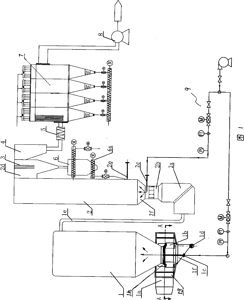
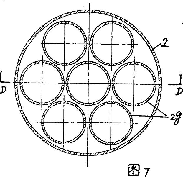
[0022] Embodiment 1, the structure of the semi-dry flue gas purification device with independent desuperheating tower in this embodiment can be referred to in Fig. 1, and it comprises a reaction tower with the inlet smoke box 2a of the bottom, the flue gas outlet 2d of the top 2. At the bottom of the reaction tower, there is a Venturi-shaped tower wall with a constriction section 2b and a diffusion section 2f, which can make the flue gas inject at low resistance and high speed, and set two on the tower wall below the diffusion section 2f. The first-stage water spraying device 2c, the nozzle pipe 2e for dry lime powder and returned ash is provided on the tower wall above the diffusion section 2f, and the inertial separator 3 and activated carbon mixing are sequentially connected between its flue gas outlet 2d and the induced draft fan 5 device 5, bag filter 7, and the detector (not shown in the figure) that can measure temperature and acidity on-line; What is different from exis...
Embodiment 2
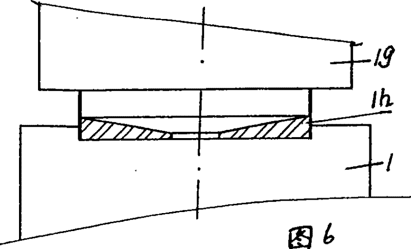
[0034] Embodiment 2, the structure of the semi-dry flue gas purification device that this embodiment has independent desuperheating tower can be seen from Fig. 1 and Fig. 3, and its difference with embodiment 1 is: this embodiment has independent The semi-dry flue gas purification device of the desuperheating tower is equipped with a flow equalization device on the inner wall 1h of the flue gas inlet end of the desuperheating tower. The device includes a boiler flue gas inlet pipe 1a installed on the inner wall of the flue gas inlet end 1h A circular casing 1g connected in a tangential direction, and a group of radial blades 1b distributed uniformly along the circumferential direction in the casing. The high-temperature boiler flue gas entering from the flue gas inlet port 1h of the desuperheating tower 1 passes through the gap between two adjacent blades 1b, and the flue gas is evenly dispersed into the desuperheating tower without bias flow; therefore, the flue gas and desupe...
Embodiment 3
[0035] Embodiment 3, present embodiment has the structure shown in Fig. 2 and Fig. 4~Fig. The difference is that it includes a volute casing 1g installed on the inner wall of the flue gas inlet end 1h of the desuperheating tower, which is in tangential communication with the boiler flue gas inlet pipe 1a, and a set of self-centered casings in the casing. Make the blade 1b that tangentially diverges outward. The high-temperature boiler flue gas entering from the flue gas inlet port 1h of the desuperheating tower 1 also passes through the gap between two adjacent blades 1b, and rotates along the tangential direction of the blades to enter the desuperheating tower. After the exchange, the temperature is lowered, and the cooling effect is good. At the same time, the fly ash in the flue gas is separated immediately, and the concentration of the flue gas dust is also reduced by 5-10%. The separated fly ash sinks in the tower, enters the ash hopper 1f at the bottom, and is discharge...
PUM
 Abstract
Description
Claims
Application Information
 - R&D
- Intellectual Property
- Life Sciences
- Materials
- Tech Scout
- Unparalleled Data Quality
- Higher Quality Content
- 60% Fewer Hallucinations
Browse by: Latest US Patents, China's latest patents, Technical Efficacy Thesaurus, Application Domain, Technology Topic, Popular Technical Reports.
© 2025 PatSnap. All rights reserved.Legal|Privacy policy|Modern Slavery Act Transparency Statement|Sitemap|About US| Contact US: help@patsnap.com


