Method and device for implementing polarization sensitive optical time domain reflection technology by using piezoelectric ceramic

A technology of optical time domain reflection and piezoelectric ceramics, which is applied in the field of optical fiber communication and optical fiber sensing, and can solve the problems of slow mechanical rotation, unstable additional coupling loss, and lateral shift of light.

Inactive Publication Date: 2009-01-14
BEIJING JIAOTONG UNIV
View PDF0 Cites 16 Cited by
  • Summary
  • Abstract
  • Description
  • Claims
  • Application Information

AI Technical Summary

Problems solved by technology

This use of a mechanically rotated polarizer to change the input polarization state poses many problems in practice: To extract light from the fiber and inject it back into the fiber through the rotating polarizer, a pair of self-focusing lenses must be used (like figure 1 The self-focusing lenses 4 and 5, and figure 2 The self-focusing lens 25 and 26)
The axial offset and angular inclination of the self-focusing lens group itself will bring unstable additional coupling loss, whil

Method used


Image

  • Method and device for implementing polarization sensitive optical time domain reflection technology by using piezoelectric ceramic
  • Method and device for implementing polarization sensitive optical time domain reflection technology by using piezoelectric ceramic
  • Method and device for implementing polarization sensitive optical time domain reflection technology by using piezoelectric ceramic

Examples


Embodiment 1

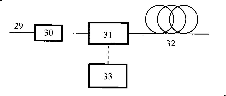
[0054] Example 1 image 3 It is a schematic structural diagram of a system using piezoelectric ceramics to realize polarization-sensitive optical time domain reflection technology. In the figure, 29 is an input optical fiber, 30 is a polarizer, 31 is a piezoelectric ceramic polarization controller, 32 is a measured optical fiber, and 33 is a control power supply, the implementation steps of this method are: cancel the mechanically rotating polarizer and the optical path composed of self-focusing lens in the original measurement optical path in the prior art, and replace it with a non-rotating piezoelectric ceramic polarization controller 31 to change the measured optical fiber 32 the input polarization state; then place a polarizer 30 in front of the piezoelectric ceramic polarization controller 31, both as a polarizer and as an analyzer, to ensure that the polarization and analyzer coordinate systems are consistent; the piezoelectric ceramic polarization controller 31 Use pie...

Embodiment 2

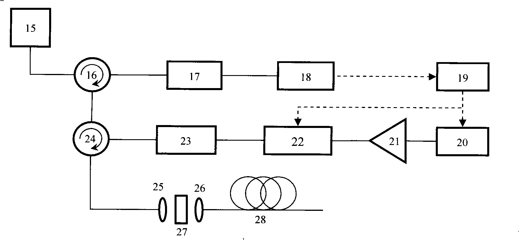
[0055] Example 2 Figure 4 It is a structural schematic diagram of a polarization-sensitive optical time-domain reflectometry device using piezoelectric ceramics, which consists of a short pulse optical signal source 34, a fiber circulator 35, a fiber polarizer 36, a piezoelectric ceramic polarization controller 37 and a detector 38 , and a computer control circuit 39 etc., the optical fiber to be tested is 40. The short-pulse optical signal source 34 sends out a short-pulse optical signal; the short-pulse optical signal enters the fiber optic polarizer 36 through ports 1 and 2 of the optical fiber circulator 35, so that the short-pulse optical signal remains in a linearly polarized state and is output to the piezoelectric ceramic Polarization controller 37; the short-pulse optical signal that enters the piezoelectric ceramic polarization controller 37, its output polarization state changes with the change of the piezoelectric ceramic driving voltage, and is injected into the ...

Embodiment 3

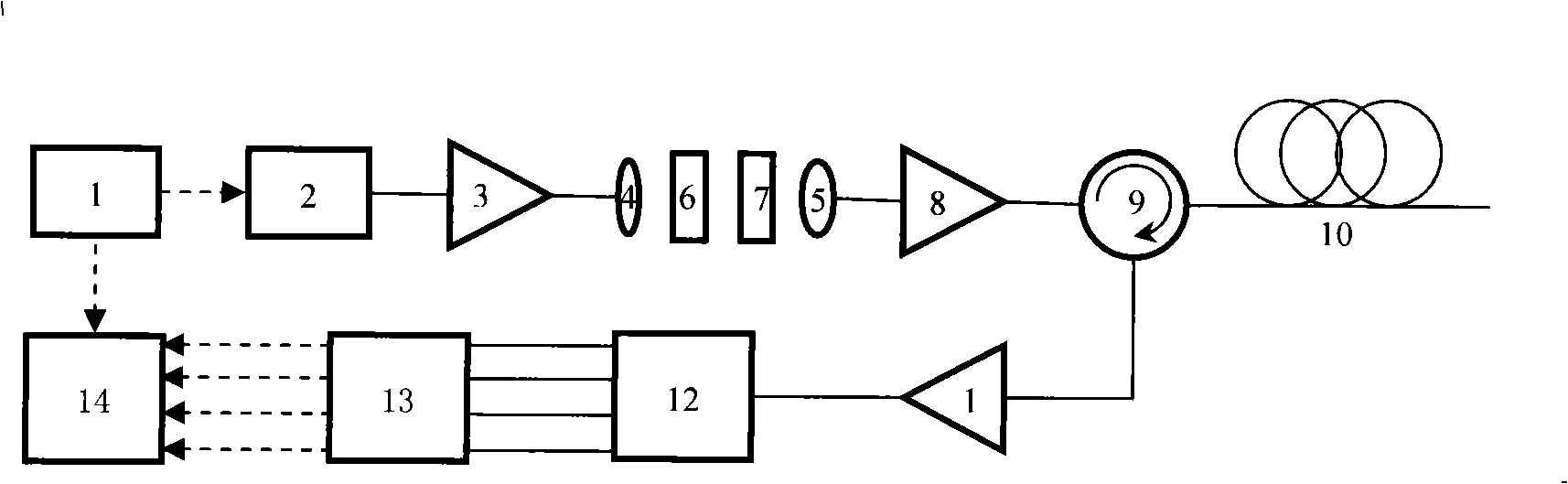
[0058] Example 3 as Figure 6 Shown is a method and device for polarization-sensitive optical time-domain reflectometry realized by piezoelectric ceramics. it is in Figure 4 On the basis of the laser 46, a programmable signal generator 47, an external modulator 48, and an erbium-doped fiber amplifier 49 together form a short-pulse optical signal source. Laser 46 sends direct current light, and is connected with the light input end of external modulator 48; Under the control of the electric signal of 47, the DC light input from the laser 46 is modulated, and an optical pulse is output. This light pulse enters the erbium-doped fiber amplifier 49 for amplification, then enters the fiber polarizer 51 through ports 1 and 2 of the fiber circulator 50, and the light passing through the fiber polarizer 51 remains in a linearly polarized state, and is output to the piezoelectric ceramic polarization control Device 52. The output polarization state of the light pulse entering the p...


PUM


Abstract

The invention discloses a method and a device which realize the time-domain reflection technique of polarized sensitive lights by utilizing piezoelectric ceramics and are characterized in that an unspinnable piezoelectric ceramic polarization controller is used in a measuring light path, and an optical fiber polarizer is arranged before the piezoelectric ceramic polarization controller and taken as both a polarizer and an analyzer. The implementation method of the invention is that the piezoelectric ceramic polarization controller changes light pulses from a short pulse light signal source into a known polarization state under the control of a computer, injects the light pulses into an optical fiber to be detected, and generates backscattering lights; only a photoelectric detector and an algorithm are needed to detect the polarization state change of the returned backscattering lights, thus realizing the distributed measurement of parameters of the optical fiber and the environment. The method and device do not need mechanically spinning devices, have the advantages of accurate measurement, good repetitiveness and quick and convenient operations, etc., and can be widely used in the distributed measurement of the parameters of the optical fiber and the fields of distributed fiber sensors, etc.

Description

technical field [0001] The invention relates to a method and a device for realizing polarization-sensitive light time-domain reflection technology by using piezoelectric ceramics as a polarization control unit, and belongs to the technical fields of optical fiber communication and optical fiber sensing. Background technique [0002] With the rapid development of optical fiber communication and optical fiber sensing technology, it is very important to monitor optical fiber communication lines and measure external environmental factors by measuring optical fiber parameters. Polarization characteristics are one of the basic characteristics of light. When light is transmitted in an optical fiber, it is affected by the parameters of the fiber itself (such as inherent birefringence, twist rate, and polarization mode dispersion, etc.), and its polarization state will change. At the same time, changes in the external environment Bending, twisting, and stress changes in the optical f...

Claims


Application Information

Patent Timeline
IPC IPC(8): G01M11/02G01D5/30G02F1/035
Inventor 吴重庆李政勇杨双收
Owner BEIJING JIAOTONG UNIV
Why Eureka
Try Eureka