Process for production of carbon nanotube aggregates, carbon nanotube aggregates, catalyst particle dispersion membrane, electron emitters, and field emission displays

A technology of carbon nanotubes and manufacturing methods, applied in the field of carbon nanotube aggregates, can solve the problems of coarse alloy particle size, inability to maintain particle size, and inability to obtain carbon nanotube aggregates, etc., to achieve improved uniformity and high catalyst efficiency Effect

Inactive Publication Date: 2009-02-11
NIKON CORP
View PDF8 Cites 17 Cited by
  • Summary
  • Abstract
  • Description
  • Claims
  • Application Information

AI Technical Summary

Problems solved by technology

The method described in Document 4 is a method of adjusting the alloy composition ratio of the alloy catalyst film to perform desired density control. However, there is a problem that the alloy grain size grows and becomes coarse due to heating, and the initial grain size cannot be maintained. As a result, a carbon nanotube aggregate composed of the desired number of graphene sheets cannot be obtained

Method used


Image

  • Process for production of carbon nanotube aggregates, carbon nanotube aggregates, catalyst particle dispersion membrane, electron emitters, and field emission displays
  • Process for production of carbon nanotube aggregates, carbon nanotube aggregates, catalyst particle dispersion membrane, electron emitters, and field emission displays
  • Process for production of carbon nanotube aggregates, carbon nanotube aggregates, catalyst particle dispersion membrane, electron emitters, and field emission displays

Examples


Embodiment 1

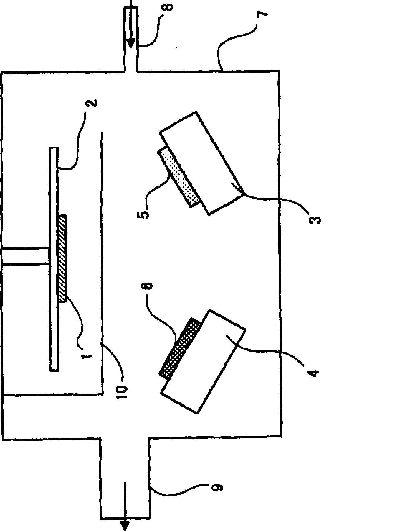
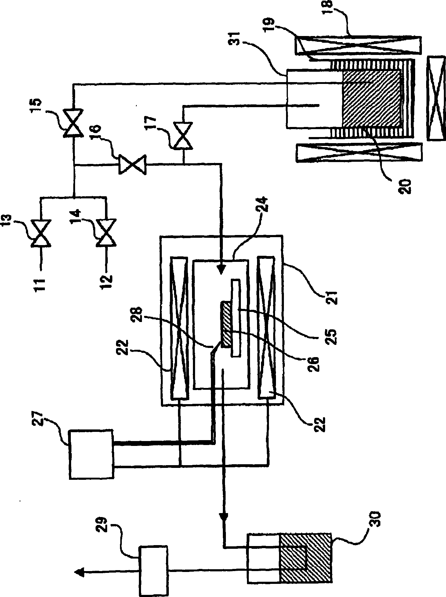
[0123] By forming a dispersed film of catalyst particles with various metal catalyst particle densities on a quartz glass substrate by simultaneous sputtering, a reduction step and a CVD step are performed to produce carbon nanotubes with a high yield and controlled growth density. Examples of nanotube aggregates are described below.

[0124] Target A uses Al 2 o 3 For the sintered body, a Fe-W powder metallurgy target (Fe / W=2 / 1) was used for target B. In addition, although Fe was used as the main catalyst particle, W was used as the co-catalyst particle, Al 2 o 3 As for the combination of barrier particles, the same effect can be obtained with the combination of the above-mentioned other metals.

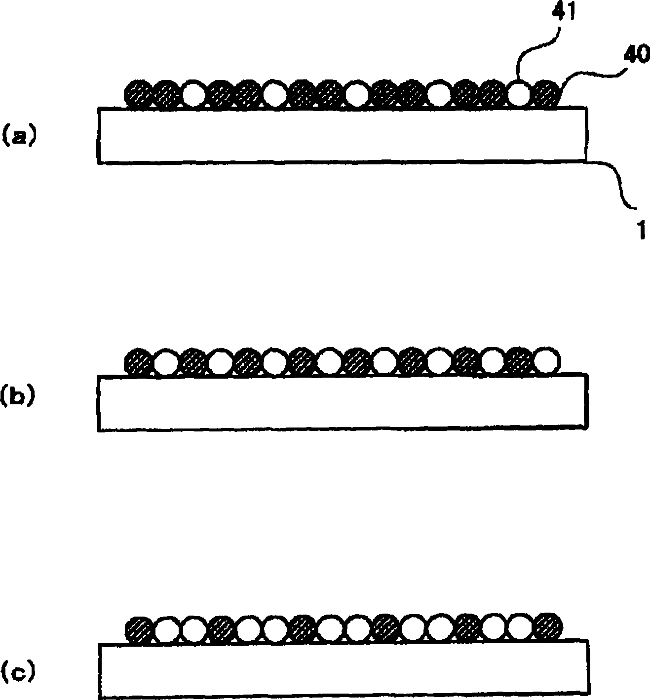
[0125] A high-purity two-layer carbon nanotube aggregate can be obtained by forming a catalyst particle dispersion film such that the particle diameter of the metal catalyst particles immediately before carbon nanotube growth is approximately 9 to 10 nm. This fact is the insigh...

Embodiment 2

[0136] In this embodiment, photocatalyst particles are supported on carbon nanotube aggregates with a ratio of 50% or more of the two-layered carbon nanotubes produced in embodiment 1 and controlled to various growth densities. described as follows.

[0137]

[0138] TiO with visible light responsiveness 2-x N x The powder (primary particle size: 5 to 10 nm) was dispersed in a propanol solvent at a ratio of 10% by weight. 100 mL of the obtained dispersion was poured into a beaker. The five types of aggregates of carbon nanotubes shown in FIG. 6 produced in Example 1 were immersed in the beaker filled with the dispersion liquid, and left to stand for 1 hour. Then, the carbon nanotube assembly was taken out and dried at 100°C for 1 hour to make the photocatalyst TiO 2-x N x The particles are supported on the aggregates of carbon nanotubes. This is called a photocatalyst element substrate. In this example, TiO was used in which part of the oxygen atoms of titanium dioxid...

Embodiment 3

[0152] Example 3 relates to a field emission display device (electron emission element) using the carbon nanotube assembly (carbon material) of the present invention as an electron source. 9 is a schematic cross-sectional view of the display, 51 is an emitter electrode, 52 is an insulator, 53 is a gate electrode, 54 is an electron source, 55 is a phosphor, and 56 is a DC power supply.

[0153] In the field emission display device of Example 3, the electron source 54 is composed of the aggregate of carbon nanotubes of the present invention. Electrons are emitted from the electron source 54 on the emitter electrode 51 biased to a negative voltage by a DC power supply 56 due to a field emission phenomenon, and collide with the opposing phosphor 55 to generate fluorescence. At this time, the gate electrode 53 has a function of pulling electrons from the electron source 54 as an electrode for pulling electrons. In addition, the insulator 52 has a function of preventing discharge b...


PUM

PropertyMeasurementUnit
particle diameteraaaaaaaaaa

Abstract

A method for producing a carbon nanotube assembly, the method controlling a growth density of carbon nanotubes on a substrate, includes: a step for preparing a catalyst particle dispersed film-formed substrate including a catalyst particle dispersed film in which metal catalyst particles having a predetermined particle diameter are dispersed among barrier particles; and a thermal CVD step for growing carbon nanotubes from the metal catalyst particles serving as starting points by heat decomposition of an organic compound vapor.

Description

technical field [0001] The present invention relates to a production method and a carbon nanotube aggregate for controlling the growth density of a carbon nanotube aggregate composed of an aggregate of carbon nanotubes having a uniform number of graphene sheets. It also relates to a catalyst particle dispersed film for growing carbon nanotubes, and an electron emission device and a field emission display using the carbon nanotube aggregate. Background technique [0002] Carbon nanotubes are a type of fibrous carbon with a graphene sheet stacked into an annual ring structure. Although the diameter is only 0.43nm to several 10nm, the length can reach 100nm to several mm, and it is a nanometer with a large aspect ratio. carbon fiber. The so-called "graphene sheet" here refers to the crystals constituting graphite and sp 2 The carbon atoms of the hybrid orbitals are located in the layers at the vertices of the regular hexagon. [0003] In most cases, carbon nanotubes consisti...

Claims


Application Information

Patent Timeline
Patent Type & Authority Applications(China)
IPC IPC(8): C01B31/02B01J21/18B01J23/85B01J35/02B82B1/00B82B3/00H01J1/30H01J31/12
CPCB82Y30/00C01B31/0233B01J35/023B01J35/004B01J37/18C01B2202/04H01J2201/30469Y10T428/24612H01J9/025B82Y10/00C01B2202/02H01J2329/00C01B2202/08B01J37/34B82Y40/00B01J21/185B01J23/85B01J35/006B01J23/888C01B32/162
Inventor 瀧优介筱原清晃菊池牧子
Owner NIKON CORP
Why Eureka
Try Eureka