
Separation method for light hydrocarbon products in MTO/MTP reaction products

A technology for reaction products and separation methods, applied in distillation purification/separation, hydrocarbon purification/separation, chemical instruments and methods, etc., can solve problems such as increased equipment investment, energy consumption, and complex separation processes

Inactive Publication Date: 2009-02-18
WISON ENG
View PDF1 Cites 71 Cited by
  • Summary
  • Abstract
  • Description
  • Claims
  • Application Information

AI Technical Summary

Problems solved by technology

Since the overhead stream of the deethanizer does not contain C3 and C3 or above components, if C3 and above components are introduced as absorbents, a new rectification tower will be added for the separation of absorbents, resulting in separation Complex process, increased equipment investment and energy consumption

Method used


Image

  • Separation method for light hydrocarbon products in MTO/MTP reaction products

Examples


Embodiment 1

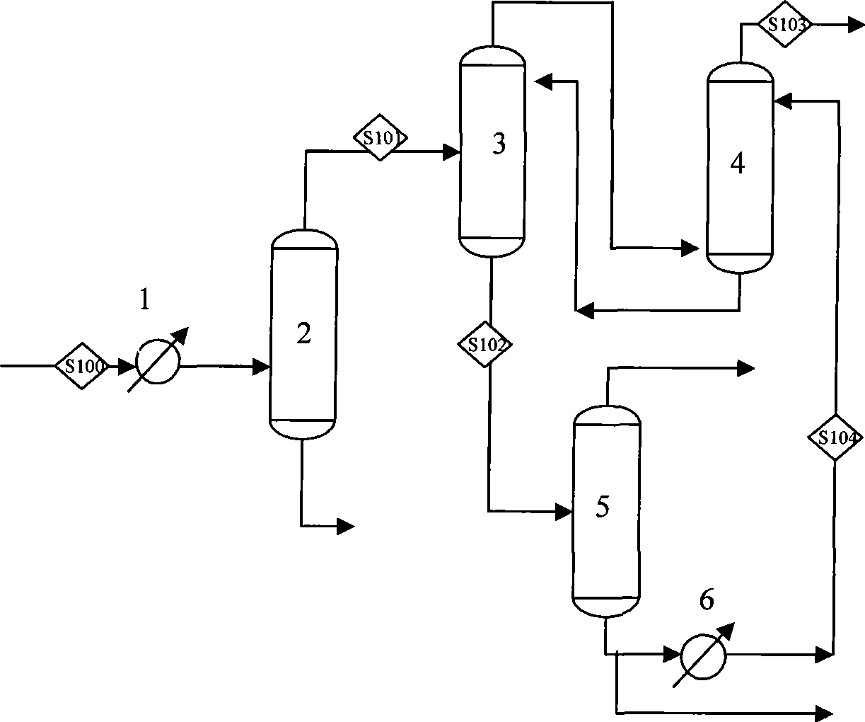
[0027] like figure 1 As shown, a certain reaction product is compressed, washed with water, washed with alkali, deoxidized and dried before entering the separation system. The gas is separated from carbon 3 and carbon 4 through the high and low pressure depropanizer, the still liquid of the low pressure depropanizer enters the debutanizer for separation of carbon 4 and carbon 5, and the gas phase at the top of the high pressure depropanizer is compressed to 3MPa. S100 is cooled to -20°C and then enters the deethanizer 2 for carbon 2 and carbon 3 separation, and the product from the tower still enters the propylene tower for separation to obtain polymer-grade propylene products. Deethanizer 2 tower top carbon two and lighter fractions S101 enter the absorption and distillation tower 3 for absorption and separation, the top gas phase is absorbed in the oil absorption tower 4, and the oil absorption tower 4 tower top S103 is methane, hydrogen and other light components Divide th...

Embodiment 2

[0032] like figure 1As shown, a certain reaction product is compressed, washed with water, washed with alkali, deoxidized and dried before entering the separation system. The gas S100 is cooled to -20°C and then enters the deethanizer 2 for C2 and C3 separation, the product from the tower still enters the depropanizer for C3 / C4 separation, and the top product of the depropanizer enters the propylene tower to obtain polymerization grade propylene , the still liquid of the depropanizer enters the debutanizer for C4 / C5 fraction separation. Deethanizer 2 tower top carbon two and lighter fractions S101 enter the absorption and distillation tower 3 for absorption and separation, and the tower top gas phase is recovered in the oil absorption tower 4, and the oil absorption tower 4 tower top S103 is light such as methane and hydrogen. Component gas, the tower still returns to absorb the distillation tower 3 as a rich absorbent, and the carbon two fraction S10 of the absorption distil...


PUM


Abstract

The invention relates to a method of separating light hydrocarbon product from MTO / MTP reaction product. The steps of the method comprise: pretreating and sending the MTO / MTP reaction product to a deethanizer for the clean separation of C2 / C3; sending gas phase on the top of the deethanizer to an absorption-distillation tower which uses rich absorbent from an oil absorption tower for absorption. The bottom product of the deethanizer enters into a subsequent separating system. The top production of the absorption-distillation tower is cooled and then is sent to the oil absorption tower. The oil absorption tower takes ethane as poor absorbent to separate ethylene from the top product of the absorption-distillation tower. Other light gas is discharged from the top. The bottom product serves as the rich absorbent and returns to the absorption-distillation tower. The bottom product of the absorption-distillation tower goes into an ethylene tower. Bottom ethane components serve as the poor absorbent and go into the oil absorption tower after cooling. Compared with the prior art, the invention has the advantages of less investment and high material recovery rate.

Description

technical field [0001] The invention relates to the fields of coal chemical industry, natural gas chemical industry and petrochemical industry, in particular to a method for separating light hydrocarbon products in MTO / MTP reaction products. Background technique [0002] Ethylene and propylene are the most important basic raw materials of petrochemical industry and play an important role in the development of national economy and society. Hydrocarbon thermal cracking is one of the main methods for producing ethylene. However, with the increasing demand for ethylene and the increasingly tight oil supply, a variety of process technologies for producing or increasing ethylene and propylene have been developed, such as oxides, especially Methanol and other alcohols are used as raw materials to produce light olefins (MTO) and propylene (MTP). These technologies avoid or reduce the use of petroleum resources to produce ethylene and propylene products, and have great development p...

Claims


Application Information

Patent Timeline
IPC IPC(8): C07C11/02C07C1/20C07C7/04C07C7/00
CPCY02P30/20Y02P30/40
Inventor 李立新倪进方刘长旭杨林林徐国辉
Owner WISON ENG
Learn More