Wind power generator cooled by solar injection

A wind generator, jet-type technology, applied in the direction of wind generator components, wind engines, wind motor combination, etc., can solve the problem that it is difficult to meet the high-efficiency and reliable work requirements of high-power wind generators, and cannot meet the requirements of high-power wind power generation High efficiency, reliable operation, great influence of cooling temperature and other problems, to achieve remarkable environmental protection effect, good environmental protection benefit and good cooling effect

Inactive Publication Date: 2009-03-25
南京韩威南冷制冷集团有限公司
View PDF1 Cites 14 Cited by
  • Summary
  • Abstract
  • Description
  • Claims
  • Application Information

AI Technical Summary

Problems solved by technology

Existing MW-level wind turbines are mainly cooled by water cooling, that is, by setting an air-water heat exchanger outside the engine room, the circulating water flowing through the gear box, generator and inverter heat exchanger is carried by the high-altitude high-speed airflow. The cooling system has the disadvantages of low cooling efficiency and heavy weight, and the cooling temperature is greatly affected by the environment, which can no longer meet the demanding requirements of high-power wind turbines for efficient and reliable operation.
Wind turbines that use evaporative cycle cooling such as patent ZL200610039658.9 can obtain greater cooling capacity and achieve the temperature required for the best working conditions of wind turbines, but consume additional power, which reduces the energy consumption to a certain extent. generator efficiency
In addition, the system generally uses chlorofluorocarbons as refrigerants, which are not conducive to environmental protection because they will destroy the ozone layer of the atmosphere.
It can be seen that the existing wind turbine cooling technology has been difficult to meet the high-efficiency and reliable operation of high-power wind turbines.

Method used


Image

  • Wind power generator cooled by solar injection
  • Wind power generator cooled by solar injection
  • Wind power generator cooled by solar injection

Examples


Embodiment Construction

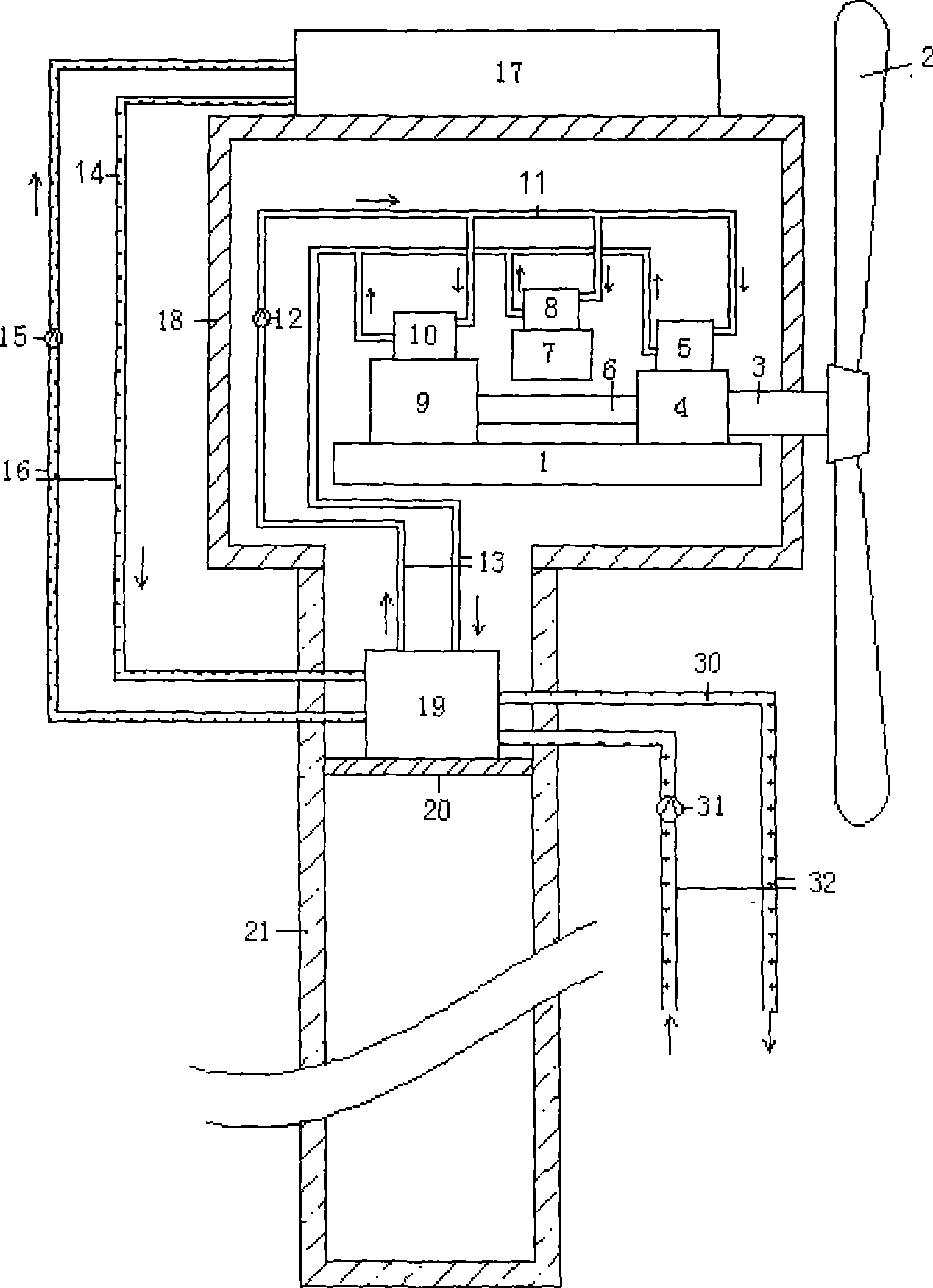
[0011] according to figure 1 As shown, the wind power generator adopting solar jet cooling of the present invention mainly includes a stand 1, a wind wheel 2, a low-speed shaft 3, a gear box 4, a gear box heat exchanger 5, a high-speed shaft 6, a control frequency converter 7, Control frequency converter heat exchanger 8, generator 9, generator heat exchanger 10, brine 11, circulation pump I 12, brine delivery pipe 13, heat storage agent 14, circulation pump II 15, heat storage agent delivery Pipe 16, nacelle cover 18, tower platform 20, tower frame 21, cooling medium 30, circulation pump III 31, cooling medium delivery pipe 32; It is characterized in that it also includes the solar heat collector 17 placed on the outer surface of the nacelle cover, and An ejector refrigerator 19 for cooling the brine 11 circulating through the gearbox heat exchanger, the control frequency converter heat exchanger and the generator heat exchanger.

[0012] When wind power generation works, th...


PUM


Abstract

The invention discloses a wind power generator adopting solar ejecting type cooling, which belongs to the technical field of wind power generator. The wind power generator mainly comprises a desk frame (1), a wind wheel (2), a slow-speed shaft (3), a gear box (4), a gear box heat exchanger (5), a high speed shaft (6), a controlling frequency converter (7), a controlling frequency converting heat exchanger (8), a generator (9), a generator heat exchanger (10), secondary refrigerants (11), a secondary refrigerant transportation pipe (13), a heat accumulator (14), a heat accumulator transportation pipe (16), cooling media (30), and a cooling media transportation pipe (32). The winder power generator is characterized in that the winder power generator also comprises a solar thermal collector (17) arranged on the outer surface of an engine room cover, and an ejecting type refrigerating machine (19) for cooling and cycling the secondary refrigerants (11) running through the gear box, the controlling frequency converter, and the generator heat exchanger (10). The wind power generator has the advantages of low electric energy consumption, good cooling effect, excellent environmental protection benefit, and the like.

Description

technical field [0001] The invention relates to a wind power generator adopting solar jet cooling, which belongs to the technical field of wind power generation. Background technique [0002] In order to achieve efficient, stable, and safe long-term operation of wind turbines, it is necessary to configure necessary cooling devices in wind turbines to ensure that components such as gearboxes, generators, and control frequency converters work within a certain temperature range. With the development of offshore wind power generation technology, the capacity of a single generator has reached 5-20MW, and the heat generated by the gearbox, generator and control frequency converter will increase sharply. How to use efficient cooling methods has become a high-power wind power generation technology. One of the key factors of application. Existing MW-level wind turbines are mainly cooled by water cooling, that is, by setting an air-water heat exchanger outside the engine room, the ci...

Claims


Application Information

Patent Timeline
Patent Type & Authority Applications(China)
IPC IPC(8): F03D9/00F03D1/00F03D11/00F03D9/25F03D80/60
CPCY02E10/722Y02E10/72
Inventor 蒋彦龙张秋王政韩毅强何舟东高伟佘阳梓朱春玲
Owner 南京韩威南冷制冷集团有限公司
Why Eureka
Try Eureka