Method for manufacturing drag reduction surface

A manufacturing method and anti-corrosion technology, which are applied in the process of producing decorative surface effects, manufacturing microstructure devices, decorative arts, etc., can solve the problems of poor stability of the surface morphology drag reduction effect, etc. Process pressure loss and cost reduction effect

Inactive Publication Date: 2009-04-08
XI AN JIAOTONG UNIV
View PDF0 Cites 12 Cited by
  • Summary
  • Abstract
  • Description
  • Claims
  • Application Information

AI Technical Summary

Problems solved by technology

[0008] Aiming at the technical problem of poor stability of surface topography drag reduction effect existing in the prior art, the present invention proposes a manufacturing method of drag reduction surface

Method used


Image

  • Method for manufacturing drag reduction surface
  • Method for manufacturing drag reduction surface
  • Method for manufacturing drag reduction surface

Examples


Embodiment 1

[0033] A method of manufacturing a drag reducing surface, comprising the following steps:

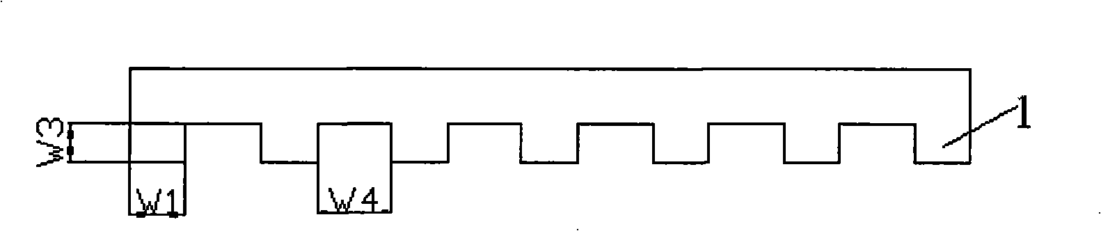
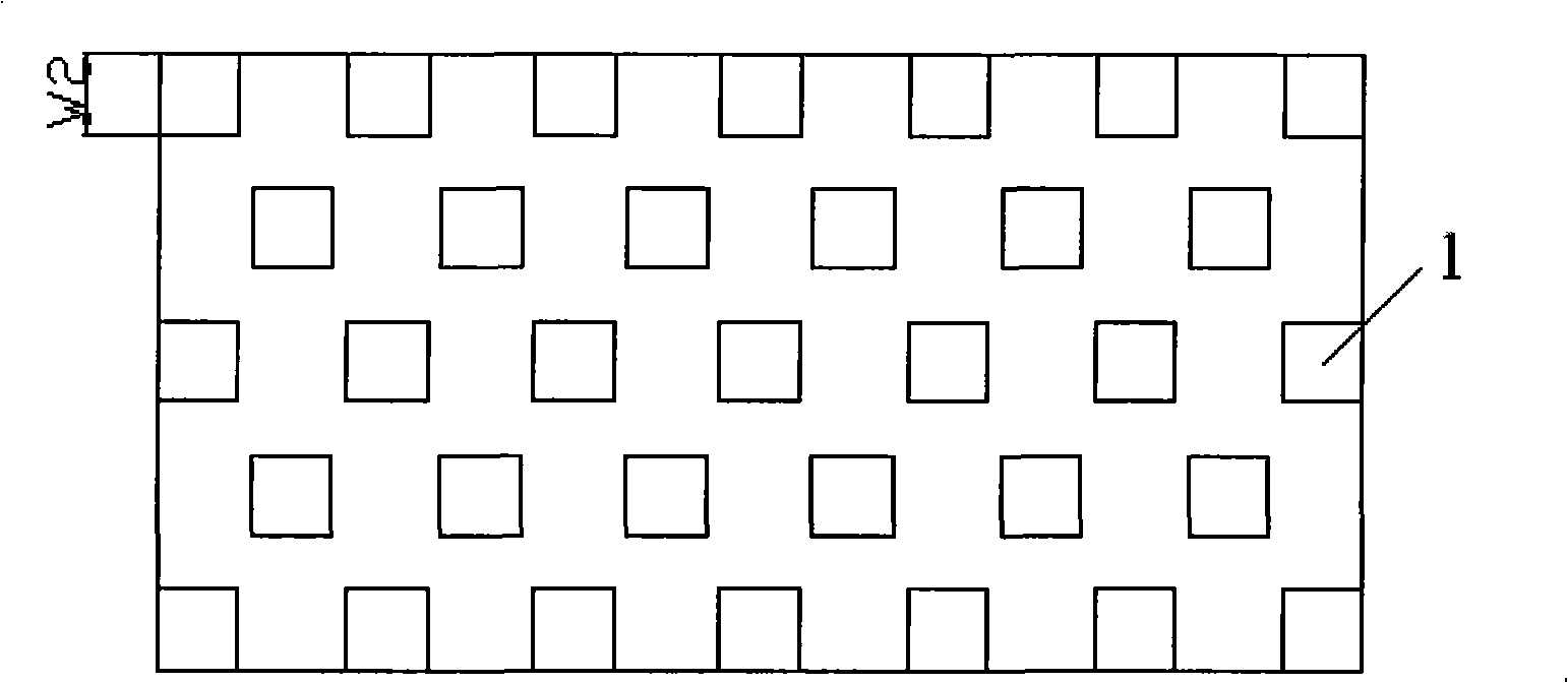
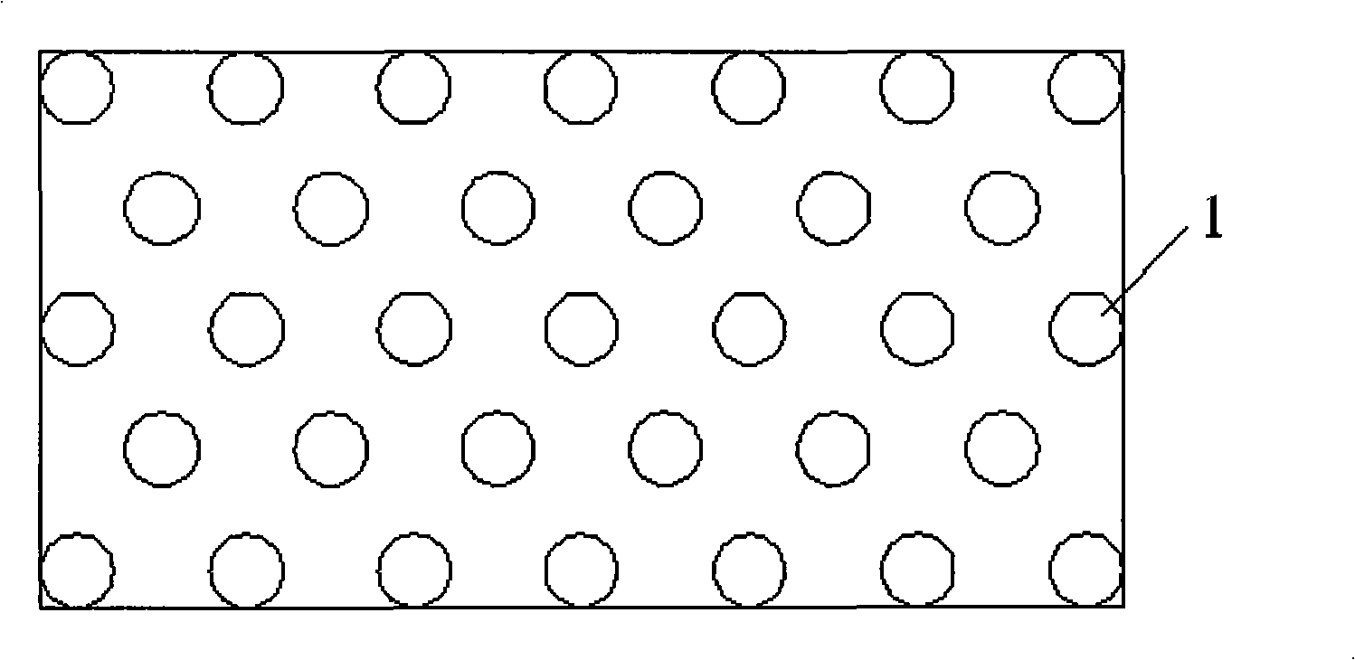
[0034] (1) Preparation of imprint template. A staggered microstructure template with a microcolumn length x width of 3 μm x 3 μm, a height of 5 μm, and a spacing of 6 μm between the microcolumns was prepared on the quartz template by wet etching.

[0035] (2) Coating of high molecular polymer corrosion inhibitor. Use a corrosion inhibitor with a viscosity of 50cp on a silicon or silicon dioxide substrate, at a low speed of 800rpm for 10s, then gradually increase the speed to 8000rpm for 45s, and the thickness of the glue layer is 5μm.

[0036] (3) Press the stencil into the anti-corrosion rubber layer, the imprint force is 75N, and the anti-corrosion rubber is polymerized and hardened by exposure to ultraviolet light, and the curing time is 10s;

[0037] (4) Release the pressure and separate the template from the silicon or silicon dioxide substrate, and the release force is 65N;

[...

Embodiment 2

[0041] A method of manufacturing a drag reducing surface, comprising the following steps:

[0042] (1) Preparation of imprint template. A staggered microstructure template with a microcolumn length x width of 60 μm x 60 μm, a height of 30 μm, and a spacing of 120 μm between microcolumns was prepared by wet etching;

[0043] (2) Coating of high molecular polymer corrosion inhibitor. SU-8 (2075) glue is used on the engineering plastic substrate, the speed at low speed is 800rpm, the time is 10s, and the speed is gradually increased to 1800rpm, the time is 45s, and the thickness of the glue layer is 30μm;

[0044] (3) Press the stencil into the anti-corrosion adhesive layer with an imprinting force of 80N, and expose the anti-corrosion adhesive to polymerize and harden to form, and the curing time is 15s;

[0045] (4) Release the pressure and separate the template from the engineering plastic substrate, and the demoulding force is 70N;

[0046] (5) Perform reactive ion etching o...

Embodiment 3

[0048] Embodiment 3 A method of manufacturing a drag-reducing surface, comprising the following steps:

[0049] (1) Preparation of imprint template. A staggered microstructure with a length of 130 μm x 130 μm in length, a width of 60 μm, and a spacing of 130 μm between the microcolumns is prepared on the master Si sheet or metal sheet by laser processing, and then cast polydimethylformaldehyde Polydimethylsiloxane PDMS material, cured and peeled off to obtain a polydimethylsiloxane PDMS material template;

[0050] (2) Coating of high molecular polymer corrosion inhibitor. Use a corrosion inhibitor with a viscosity of 150cp on the Si wafer or metal substrate, the low speed is 600rpm, the time is 15s, the high speed is 1200rpm, the time is 35s, and the thickness of the glue layer is 60μm;

[0051] (3) Press the template into the anti-corrosion rubber layer, the imprint force is 90N, and the anti-corrosion rubber is polymerized and hardened by exposure to ultraviolet light, and...


PUM

PropertyMeasurementUnit
heightaaaaaaaaaa
heightaaaaaaaaaa
heightaaaaaaaaaa

Abstract

The invention belongs to the technical field of micro-nanometer manufacturing and relates to a method for manufacturing the surface with resistance reduction. Micron level structure arrays in alternate arrangement are designed and manufactured on the surface of a silicon substrate, a silicon dioxide substrate, an engineering plastic substrate or a metal substrate; an ultraviolet stamping photoetching technology is used as a transferring means; a template can be repeatedly used; a fluorination process is used as a surface treatment means to obtain a microstructure substrate with the function of resistance reduction; and the microstructure surface of the substrate has quite low surface energy. The method can be used for the surface of a device for a micro-electromechanical system, and can reduce the surface friction and abrasion as well as the invalidation of adhesion under a microscale; the method can be used for the surface of a conveying pipeline and a microflow device, can reduce the on-way pressure loss of a fluid in a micro-passage and the flow resistance of the fluid, and can increase flow speed; and the method can be used in aviation, spaceflight, navigation, traffic transportation and other fields, and can reduce energy consumption and consequently save energy.

Description

technical field [0001] The invention belongs to the technical field of micro-nano manufacturing, and relates to a method for manufacturing a drag-reducing surface. Background technique [0002] The energy of the navigational body in the fluid is mainly used to overcome the resistance during travel, and the resistance mainly includes frictional resistance and pressure difference resistance, among which frictional resistance accounts for the main component, which can reach 80% for underwater navigational bodies such as submarines; for such as For pipeline transportation such as oil pipelines, 80% to 100% of its energy is used to overcome the frictional resistance of fluid flowing through solid surfaces. Therefore, reducing the surface friction resistance as much as possible is the main way to increase the speed and save energy. With the development of MEMS, the scale of the mechanism is getting smaller and smaller, and the frictional resistance in the solid-liquid interface i...

Claims


Application Information

Patent Timeline
Patent Type & Authority Applications(China)
IPC IPC(8): B81C1/00
Inventor 王莉丁玉成郝秀清何仲赟宗学文卢秉恒
Owner XI AN JIAOTONG UNIV
Why Eureka
Try Eureka