Method and apparatus for electromagnetic drive of rectilinear movement

A technology of linear motion and electromagnetic drive, applied in the direction of electromagnets, electromagnets with armatures, etc., can solve the problems of hydraulic workstations occupying more space, complex hydraulic oil circuit mechanisms, and low energy conversion efficiency, and achieve high energy conversion efficiency , The effect of material cost reduction and simple efficiency

Inactive Publication Date: 2009-05-27
杨东平 +1
View PDF0 Cites 16 Cited by
  • Summary
  • Abstract
  • Description
  • Claims
  • Application Information

AI Technical Summary

Problems solved by technology

The crankshaft or eccentric mechanism is used as the energy conversion method, the mechanism is more complicated, which will inevitably affect the conversion efficiency; the linear motor uses its rotor as the working part, and must also run correspondingly with the fixed stator, which has great limitations in application; The gas pressure works to push the piston, the energy conversion efficiency is low, only one of the four strokes does work, the exhaust gas seriously pollutes the environment, and the mechanism is complicated; the energy is transmitted by hydraulic means, and the hydraulic workstation needs to take up a lot of space. Oil throttling and loss along the way also directly affect energy transfer efficiency
[0003] In addition, there is another electromagnetic linear drive method, which is to use the basic principle of the N and S poles of the magnetic field to repel each other with the same sex and attract each other with the opposite sex, and realize the continuous attraction of the N and S poles with a long distance through the excitation current or the plane layout. Repel each other to achieve the purpose of movement, or achieve the purpose of short-distance clutch (commonly used in power engineering products) through the instantaneous attraction or repulsion of the solenoid winding and the magnetic core. large application limitations

Method used


Image

  • Method and apparatus for electromagnetic drive of rectilinear movement
  • Method and apparatus for electromagnetic drive of rectilinear movement
  • Method and apparatus for electromagnetic drive of rectilinear movement

Examples


Embodiment Construction

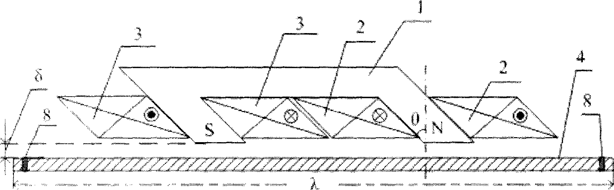
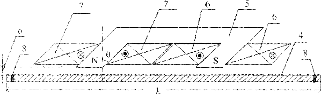
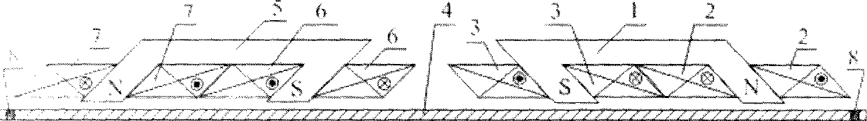
[0038] The structure of the present invention see figure 1 . The main structure is composed of a U-shaped electromagnet and a metal conductor. The two magnetic poles of the U-shaped electromagnet form an oblique angle of 45 degrees. In general, as long as the space size permits, the U-shaped electromagnet can be wound with coil windings along the three sides of the U-shaped iron core, effectively constraining the direction of the magnetic field in the iron core and reducing the loss of the magnetic field. Also for the symmetry of the design, the rationality of the use of electromagnetic energy, and the balance of the electromagnetic induction force, in actual use, two U-shaped electromagnets are combined with a metal conductor, and the layout is mirrored in the horizontal direction of the conductor. Or the object layout in the vertical direction of the conductor, as the basic power source or basic power unit. In this way, the basic power units can be combined arbitrarily acc...


PUM


Abstract

The present invention discloses a method of electromagnetic drive rectilinear motion and the device thereof, comprising a electric driver, two electromagnets in the shape of U (two feet are in parallel and form an angle at one end), a straight metal conductor provided with a location sensor which form a shape of letter 'n' with the electromagnets. Inputting two continuous periodic sawtooth wave pulse current to the device, generating periodically enhanced or weakened magnetic field on two magnetic poles of the electromagnets, generating periodic magnetic flux enhancement or weakening on touch part between conductor and magnetic poles, generating eddy current on partial conductor and the energy conversion used for conductor displacement, hence electromagnetic linear drive and power - magnetic energy - mechanical energy conversion are realized. As prime mover of rectilinear motion and or straight reciprocating motion, the device in the invention can replace existing bent axle or complex mechanism like eccentric wheel, engine oil cylinder etc., and can be applied on engine of motorcycle and electric vehicle, new electric submersible direct-drive reciprocating pump (oil well), compressor of refrigerator and air condition, high pressure pump, intercity maglev light rail, maglev train and ship injection propulsion pump etc. as a new engine device.

Description

1. Technical field [0001] The invention belongs to the technical field of mechatronics, and directly converts electromagnetic energy into mechanical energy. Specifically, it belongs to a method of converting electrical energy into magnetic energy with a power electronic driver, and then converting magnetic energy into mechanical energy to form a controllable linear mechanical motion power source. The method and the device can be widely designed and applied to manufacture novel prime movers of linear motion and linear reciprocating motion. 2. Background technology [0002] Analysis of the power source of linear motion, especially linear reciprocating motion, is generally obtained by converting the crankshaft or eccentric wheel mechanism driven by a rotating motor, or directly generated by a linear motor, or driven by gas pressure as power to drive the cylinder piston to perform linear motion, or by hydraulic means The power is transmitted to push the piston of the cylinder to...

Claims


Application Information

Patent Timeline
Patent Type & Authority Applications(China)
IPC IPC(8): H01F7/18H01F7/08
Inventor 杨东平
Owner 杨东平
Why Eureka
Try Eureka